Heat transfer system for a receptacle assembly

a heat transfer system and receptacle technology, applied in the direction of insulated conductors, cables, coupling device connections, etc., can solve the problems of increasing the quantity of heat generated by the transceiver module and the surrounding circuitry, increasing the difficulty of positioning the receptacle and other components on the circuit board, and increasing the quantity of electro-magnetic energy at very short wavelengths

Active Publication Date: 2010-07-27
TYCO ELECTRONICS LOGISTICS AG (CH)
View PDF61 Cites 112 Cited by
  • Summary
  • Abstract
  • Description
  • Claims
  • Application Information

AI Technical Summary

Problems solved by technology

More recently, new standards provide that the transceiver modules increase the data rate, which may create several problems that were not experienced previously.
One problem is that the transceiver modules and the surrounding circuitry will generate significantly greater quantities of heat, which should be removed in order for the electronic components to survive long term.
However, when more than one heat sink is used it may be more difficult to position the receptacle and other components upon the circuit board.
Another problem is that the transceiver modules will generate increased quantities of electro-magnetic (EM) energy at very short wavelengths.

Method used


Image

  • Heat transfer system for a receptacle assembly
  • Heat transfer system for a receptacle assembly
  • Heat transfer system for a receptacle assembly

Examples


Embodiment Construction

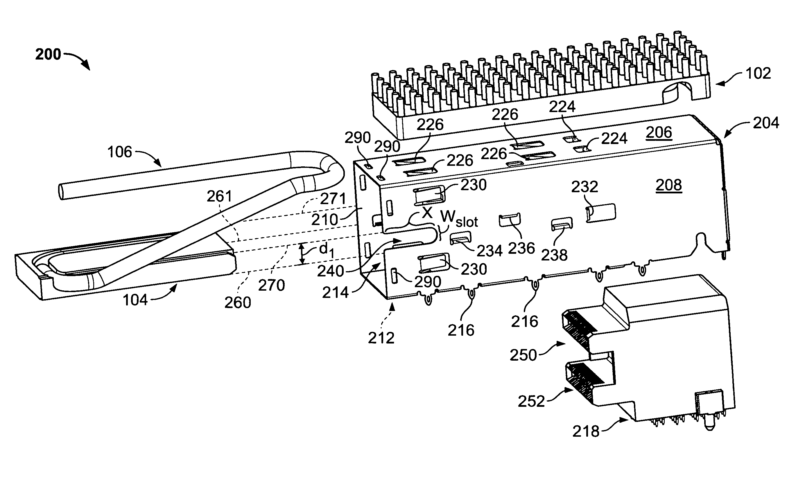
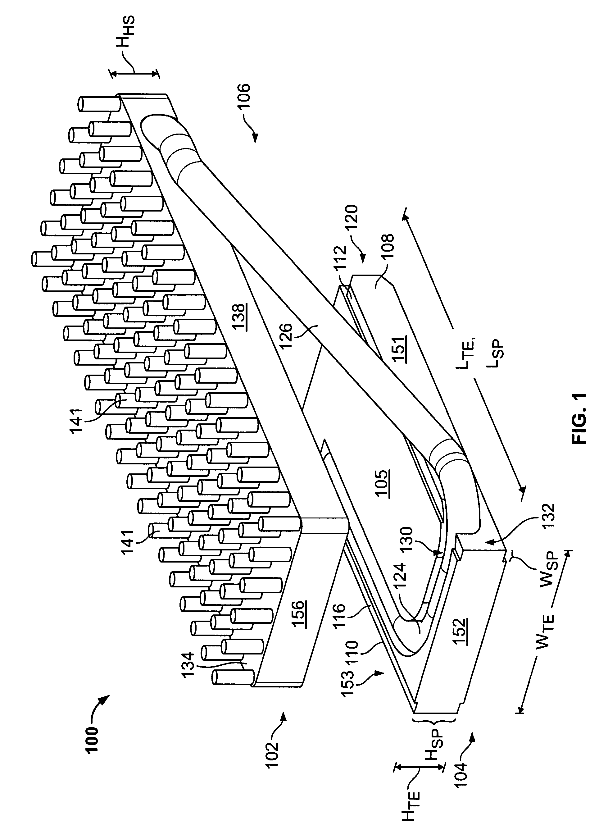
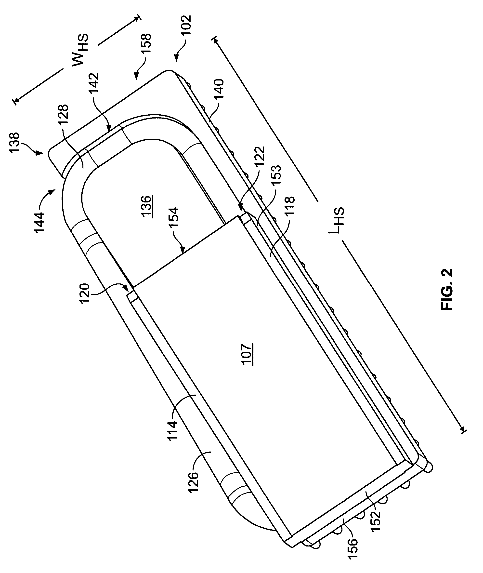
[0019]FIGS. 1 and 2 illustrate a heat transfer system 100 that includes a heat sink 102 coupled to an energy transfer element 104 via a thermally conductive bar 106. In the illustrative embodiment, transfer element 104, thermally conductive bar 106, and heat sink 102 are separate components bonded together to form heat transfer system 100. Alternatively, the thermally conductive member 106 may be integrally formed with heat sink 102 and / or transfer element 104. When installed into a receptacle assembly 200 (FIG. 3), the components of heat transfer system 100 operate to absorb, transfer, and dissipate thermal energy emitted from at least one electronic module.

[0020]Transfer element 104 may be formed from a thermally conductive metal alloy (e.g., copper alloy) and shaped into a substantially rectangular block having a width WTE, a length LTE, and a height HTE. Transfer element 104 has a top surface 105, a bottom surface 107, a front surface 152, a rear surface 154, and side surfaces 1...


PUM


Abstract

A receptacle assembly includes a housing that is configured to hold an electrical module. An energy transfer element, which is held by the housing, is positioned to directly engage the electrical module. The transfer element absorbs thermal energy produced by the electrical module. The receptacle assembly also includes a heat sink that is remotely located from the transfer element. A thermally conductive member extends between the heat sink and the transfer element to convey thermal energy therebetween.

Description

BACKGROUND OF THE INVENTION[0001]The invention relates generally to an electronic receptacle assembly, and more particularly, to a receptacle which is mounted on a circuit board and configured to have one or more transceiver modules plugged into the receptacle.[0002]Various types of fiber optic and copper based transceivers that permit communication between electronic host equipment and external devices are known. The transceivers may be incorporated into modules that can be pluggably connected to the host equipment to provide flexibility in system configuration. The modules are constructed according to various standards for size and compatibility, one standard being the Small Form-factor Pluggable (SFP) module standard.[0003]The SFP module is plugged into a receptacle that is mounted on a circuit board within the host equipment. The receptacle includes an elongated guideframe, or cage, having a front that is open to an interior space, and an electrical connector disposed at a rear ...

Claims


Application Information

Patent Timeline
Patent Type & Authority Patents(United States)
IPC IPC(8): H05K7/20H01R13/64H02B1/01G02B6/36F28F7/00
CPCG02B6/4246H01R13/6582H01R13/6586H01R13/659
Inventor PHILLIPS, MICHAEL J.HENRY, RANDALL ROBERTMURR, KEITH MCQUILKIN
Owner TYCO ELECTRONICS LOGISTICS AG (CH)
Why Eureka
Try Eureka