Stamping in-line crack detection system and method

a detection system and stamping technology, applied in the field of stamping in-line crack detection system and method, can solve problems such as cracks, common problems, and components that eventually fail during use, and contribute to cracks

Inactive Publication Date: 2010-07-27
HONDA MOTOR CO LTD
View PDF14 Cites 5 Cited by
  • Summary
  • Abstract
  • Description
  • Claims
  • Application Information

AI Technical Summary

Benefits of technology

[0013]In this particular embodiment, a number of support arms extend across the idle station to provide a rigid surface on which to support the body panels as they travel from the preceding press to the next successive press. These support arms effectively block light from the backlighting

Problems solved by technology

Defects, particularly cracks, are a common problem inherent in component stamping.
Defects in the material itself may also cause or contribute to the existence of cracks.
Cracks are problematic because they result in weakened areas that may cause a component to eventually fail during use.
These cracks may also be undesirable for cosmetic reasons.
Discovery of such cracks is difficult, however, because detection is usually accomplished through visual observation of a component of interest.
Unfortunately, such cracks are not particularly amenable to visual detection for various reasons.
Further, the responsibility for crack detection often falls on the shoulders of a machine operator or anothe

Method used


Image

  • Stamping in-line crack detection system and method
  • Stamping in-line crack detection system and method
  • Stamping in-line crack detection system and method

Examples


Embodiment Construction

)

[0025]As mentioned above, for purposes of simplicity, a single illustrative and exemplary embodiment of the present invention is discussed in detail below. However, it is to be understood that the present invention is in no way limited by the illustrative embodiment.

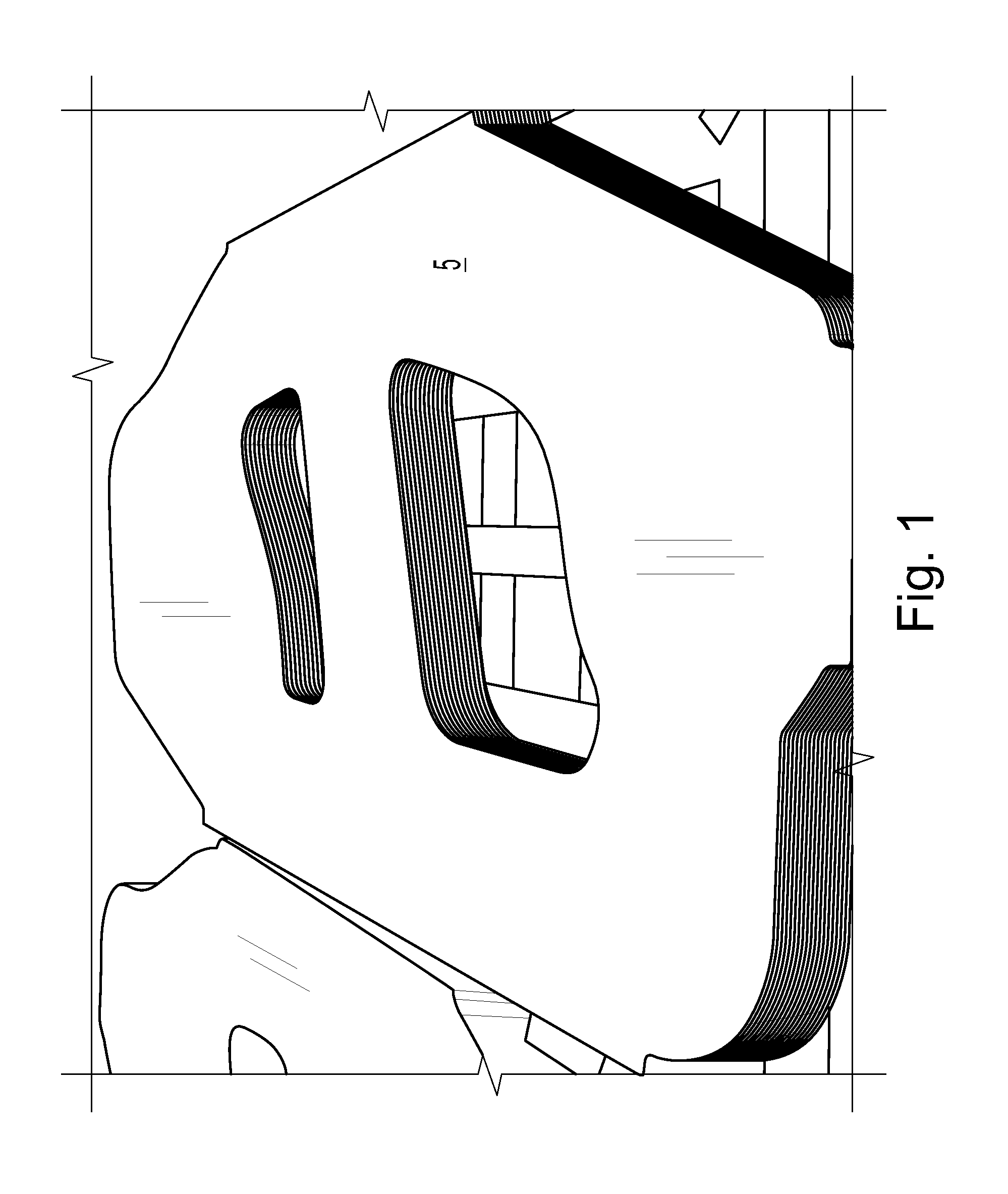
[0026]As can be observed in FIG. 1, this exemplary embodiment of the present invention is designed to inspect a vehicle body panel 5—in this particular case, a vehicle side panel. As shown in FIG. 1, the body panel 5 may still be in blank (unformed) condition as would generally be received from a blanking station. Alternatively, the blank may have already been partially formed by the first draw press 15.

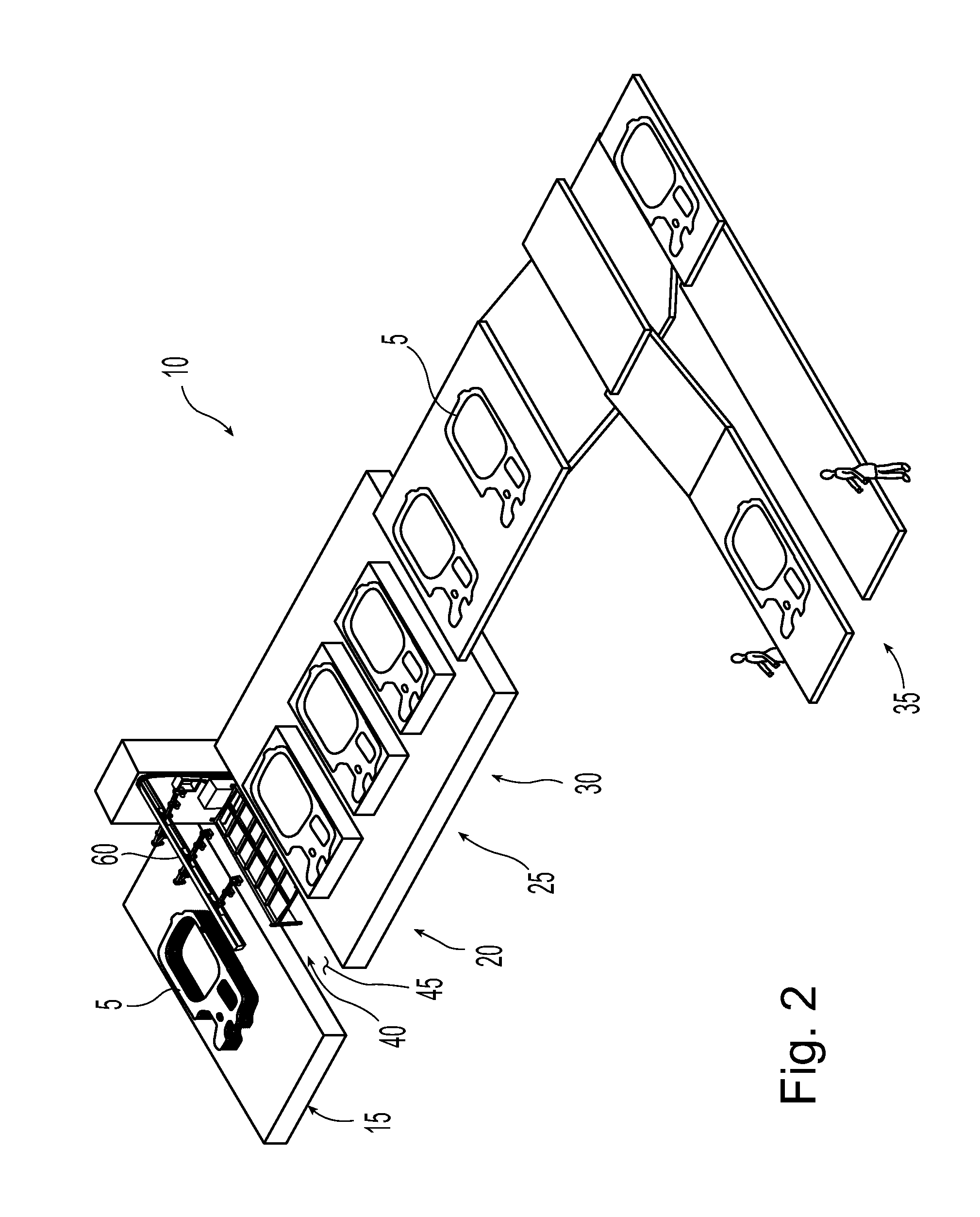
[0027]The exemplary embodiment of the present invention is installed to a to a transfer press line 10. The transfer press line 10 employs a number of in-line presses 15, 20, 25, 30 to perform various portions of the overall panel forming process. For example, as can be best observed in FIG. 2, this particular press line ...


PUM


Abstract

A system and method for automatically detecting cracks in components produced by a stamping process. A substantially uniform backlighting of the component can be produced, even when direct backlighting is partially blocked by structure used to support the component during inspection. One or more image detectors simultaneously image the component from a top side while it is backlit. One or more images of the current component are then compared to a master image of the component. Light passing through or visible through cracks in the component will cause the system to see a difference between the current image(s) of the component and the master image(s), thereby indicating a crack(s). A user is automatically notified upon detection of a crack.

Description

BACKGROUND[0001]The present invention relates to the detection of cracks and similar defects in stamped parts. More particularly, the present invention relates to the automated detection of cracks and similar defects in stamped parts during the stamping process.[0002]Defects, particularly cracks, are a common problem inherent in component stamping. Such cracks, also commonly referred to as necking or elongation, may occur as a result of forming the material used to make a particular component. Defects in the material itself may also cause or contribute to the existence of cracks. Therefore, as used herein, the term crack shall encompass any type of separation in the material of a stamped component whether caused by the stamping (forming) process, by a deficiency in the physical structure of the material itself, or some combination thereof.[0003]Cracks are problematic because they result in weakened areas that may cause a component to eventually fail during use. These cracks may also...

Claims


Application Information

Patent Timeline
IPC IPC(8): G06K9/00
CPCG01N21/8851G01N21/9515G01N21/3563G01N2021/8411G01N2201/0634
Inventor JURICH, MILANHAMILTON, MOLLYMCCANN, SHAUN
Owner HONDA MOTOR CO LTD
Why Eureka
Try Eureka