Method of producing a hollow shaft

a hollow shaft and production method technology, applied in the field of hollow shafts, can solve the problems of high complexity of tools, high cost, and limited expansion of special tools, and achieve the effects of high precision, cost-effective and rapid manufacture, and simple structur

Active Publication Date: 2010-08-03
NEUMAYER TEKFOR ENG GMBH
View PDF10 Cites 21 Cited by
  • Summary
  • Abstract
  • Description
  • Claims
  • Application Information

AI Technical Summary

Benefits of technology

[0005]It was therefore an object of the present invention to provide a hollow shaft of the above-described type, which is distinguished by its particularly simple, cost-effective and rapid manufacture and high precision.
[0009]It can be advantageous if an interference fit is provided between the internal and external profiles of the slip joint to prevent the sleeve from falling off the shaft-like section after mounting during transport, handling or assembly.
[0010]If the two profilings provided on the shaft ends have different diameters, it is advantageous if the smaller profiling is provided on the sleeve-like component and the larger profiling is integrally formed with the tubular section.
[0034]It can be advantageous to carry out a heat treatment or surface treatment, particularly soft annealing, between some of the process steps to resoften the material whose structure was hardened by cold forming in the previous steps, e.g., when producing the hollow shaft body with the first profile formed onto it, between steps b) and c), d) and e), e) and f), f) and g), and g) and h), or, when producing the sleeve, between steps d) and e).

Problems solved by technology

Such expansions can only be done in special, highly complex tools and require a substantial amount of additional work thereafter.
This would have caused substantial additional costs.

Method used


Image

  • Method of producing a hollow shaft
  • Method of producing a hollow shaft
  • Method of producing a hollow shaft

Examples


Embodiment Construction

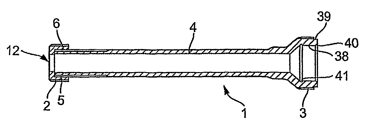
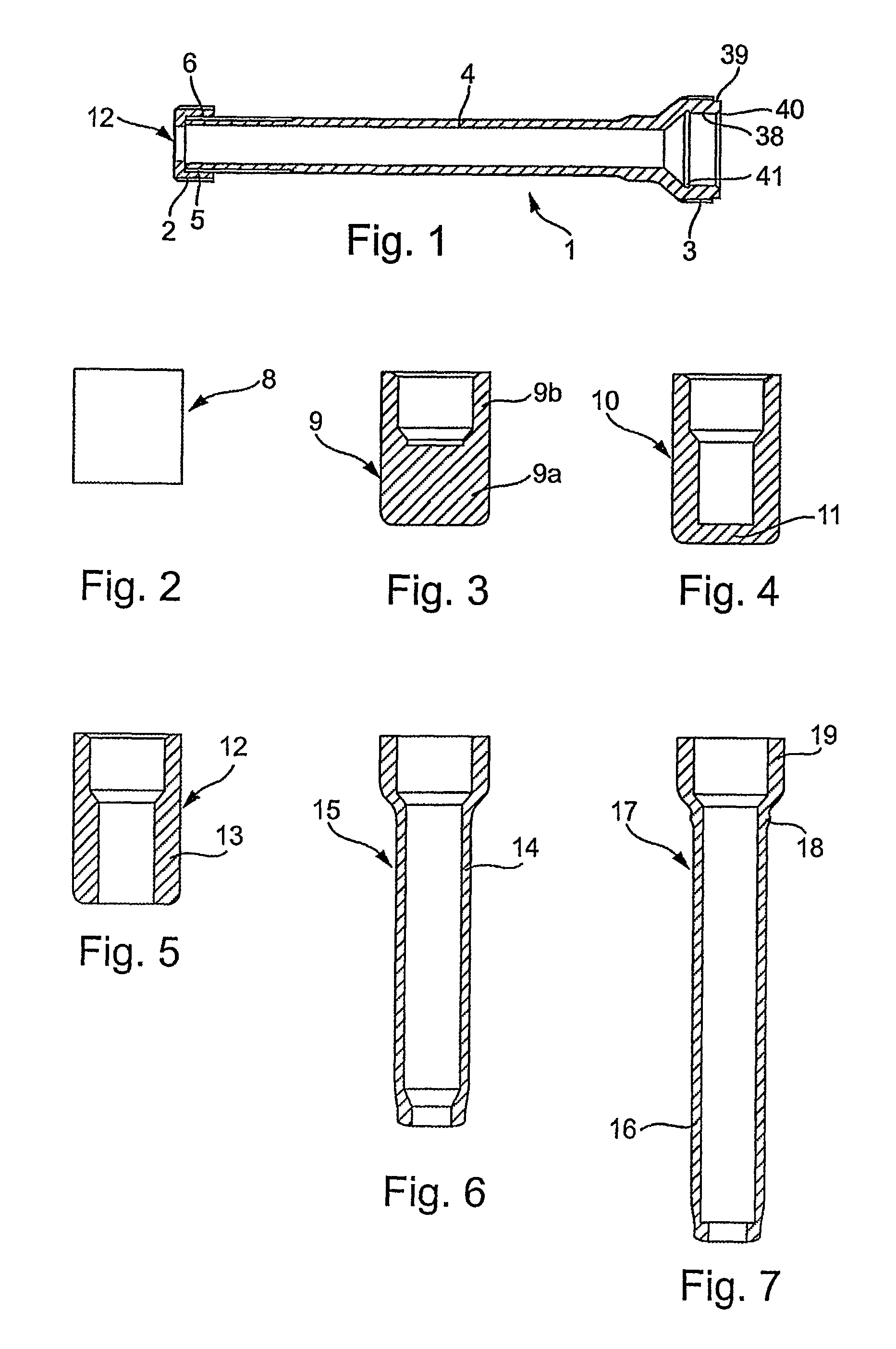
[0055]The oil pump shaft 1 shown in FIG. 1 is a hollow shaft and has external profilings at its ends in the form of shaft profilings or splines 2, 3. Between the two profile zones 2, 3 is a tubular section 4, which, at least in partial areas, has a smaller diameter than the profilings 2, 3.

[0056]In the present example, profile 3 and the tubular section 4 are formed integrally or as a single part. Sleeve 7, which is provided with profile 2, is mounted to the end of the shaft opposite profile 3 via a torque-transmitting slip joint 5, 6, which will be described in more detail below. The slip joint 5, 6 is configured as an interference fit. The tubular section 4 and the profile section 3 integrally formed therewith as well as the sleeve 7 are produced by cold forming as described below, at least with respect to their functional areas.

[0057]FIG. 2 shows a blank or workpiece 8 cut to length from bar stock, in this case by sawing.

[0058]Using a cold extrusion process, a component 9 as shown...


PUM

PropertyMeasurementUnit
diameteraaaaaaaaaa
thicknessaaaaaaaaaa
torque-aaaaaaaaaa

Abstract

A method of producing a hollow shaft having first and second profilings provided for torque transmission at respective ends thereof, wherein a shaft section between the ends has a smaller diameter than at least one of the profilings, and the hollow shaft is assembled from hollow shaft and sleeve components joined via a torque-transmitting slip joint, in which the shaft and sleeve components are each formed from cut blanks by cupping, perforating. cold extrusion and turning steps, and the respective components are assembled to each other.

Description

CROSS REFERENCE TO RELATED APPLICATIONS[0001]This application is a continuation of international patent application no. PCT / DE2006 / 001544, filed Sep. 2, 2006 designating the United States of America, and published in German on Mar. 22, 2007 as WO 2007 / 031052, the entire disclosure of which is incorporated herein by reference. Priority is claimed based on Federal Republic of Germany patent application nos. DE 10 2005 043 766.4, filed Sep. 13, 2005, and DE 10 2006 007 388.6, filed Feb. 17, 2007.BACKGROUND OF THE INVENTION[0002]The invention relates to a hollow shaft, which has external profilings for torque transmission at its two ends, e.g., splines, wedge-shaped teeth, polygonal profiles or the like, such that the shaft sections therebetween have a smaller diameter than the profilings.[0003]Hollow shafts of this type can be used to drive units such as oil pumps, where, for space reasons, the center section is thinner than the toothed ends.[0004]One proposed method to produce such sh...

Claims


Application Information

Patent Timeline
Patent Type & Authority Patents(United States)
IPC IPC(8): B21D28/00
CPCF16C3/02Y10S29/009Y10S29/047
Inventor STUECKRAD, RAINERSTRAUB, HELMUT
Owner NEUMAYER TEKFOR ENG GMBH
Why Eureka
Try Eureka