Combined accelerometer and gyroscope system

a gyroscope and accelerometer technology, applied in the direction of acceleration measurement using interia forces, turn-sensitive devices, instruments, etc., can solve the problems of increased size and cost of inter-axis alignment, high cost, and time-consuming

Inactive Publication Date: 2010-08-03
KONKUK UNIV IND COOP CORP
View PDF7 Cites 43 Cited by
  • Summary
  • Abstract
  • Description
  • Claims
  • Application Information

AI Technical Summary

Benefits of technology

[0002]The present invention relates, in general, to an accelerometer and gyroscope system, and, more particularly, to a combined accelerometer and gyroscope system, which can measure an acceleration and an angular velocity that are input in directions perpendicular to each other.

Problems solved by technology

However, such inter-axis alignment incurs a high cost and takes a lot of time in the stage of manufacturing an inertial measurement unit, and the perpendicular alignment of a gyroscope entails a more complicated procedure than an accelerometer.
The use of individual accelerometers and gyroscopes in fields, in which accelerations and angular velocities for two or more axes are used together, is disadvantageous in that the size and cost thereof are increased, and, additionally, a lot of time and effort is required to conduct alignment between a number of sensor input axes proportional to the number of sensors.
Therefore, when a plurality of accelerometers and gyroscopes for measuring inertial forces input to a plurality of axes is used, the development of inertial sensors having sensor input angles that are structurally aligned with each other using a single mechanical structure is urgently required.

Method used


Image

  • Combined accelerometer and gyroscope system
  • Combined accelerometer and gyroscope system
  • Combined accelerometer and gyroscope system

Examples


Embodiment Construction

[0017]The above and other objects, features and other advantages of the present invention will be more clearly understood from the following detailed description taken in conjunction with the accompanying drawings. Before the description of the present invention, it should be noted that the terms or words used in the present specification and claims are to be interpreted as having the meaning and concept corresponding to the technical spirit of the present invention on the basis of the principle by which the inventor can suitably define the concept of terms to describe the invention thereof in the best way. Further, it should be noted that detailed descriptions may be omitted if it is determined that the detailed descriptions of related well-known functions and constructions would make the gist of the present invention unclear.

[0018]Hereinafter, embodiments of the present invention will be described in detail with reference to the attached drawings.

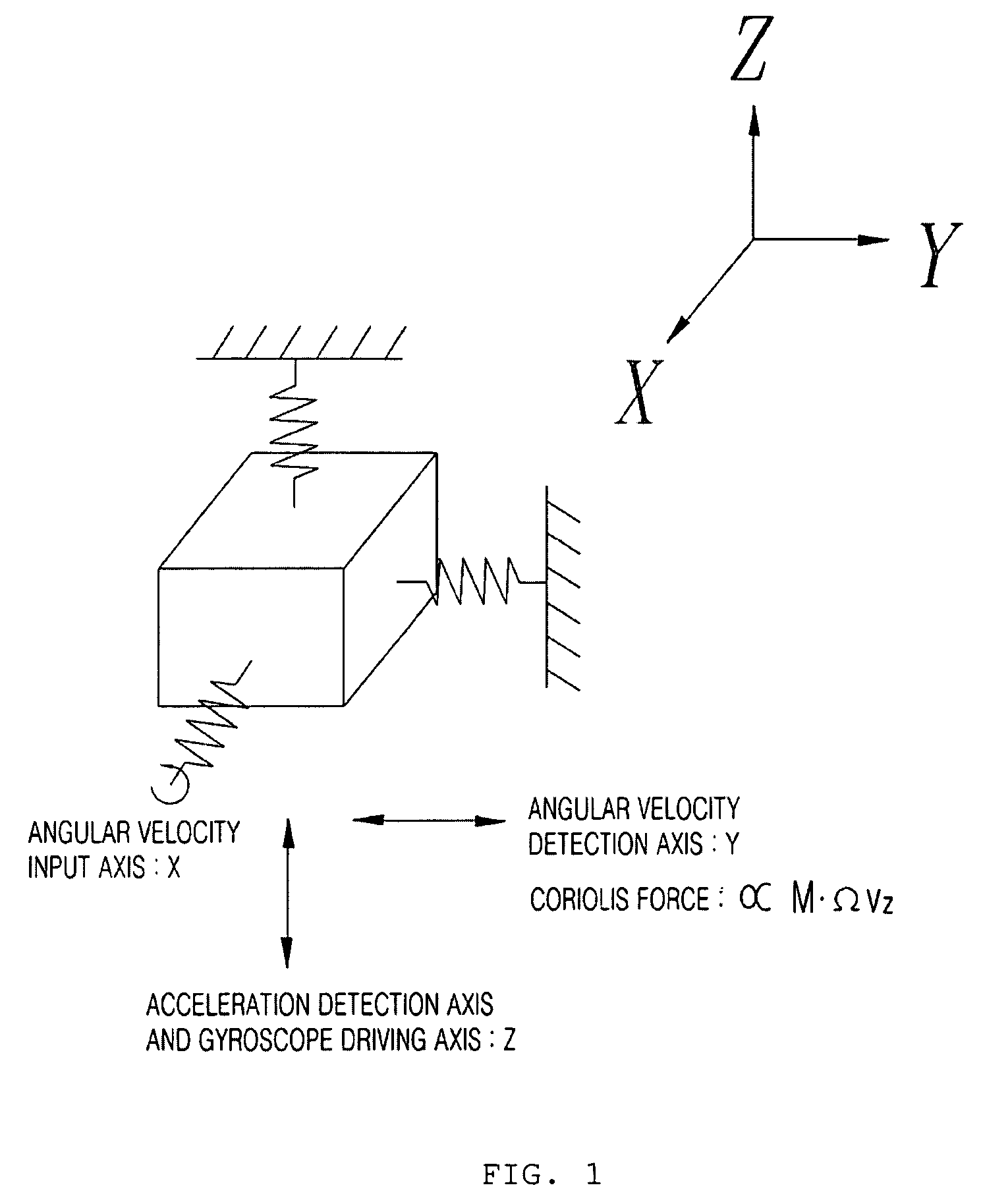
[0019]FIG. 1 is a diagram of an ex...


PUM


Abstract

An embodiment of the present invention relates to a combined accelerometer and gyroscope system. The combined accelerometer and gyroscope system includes a combined accelerometer and gyroscope for maintaining vibration of a mass body at a constant amplitude using an applied drive voltage, and detecting vibration signals in directions of an acceleration axis and an angular velocity axis. An acceleration axis vibration signal obtainment unit obtains the vibration signal in the direction of the acceleration axis. An amplitude maintenance control unit outputs an acceleration axis vibration maintenance control signal using the vibration signal. An acceleration axis driving input unit receives a voltage signal from the amplitude maintenance control unit and applies the voltage signal to the combined accelerometer and gyroscope. An angular velocity axis vibration signal obtainment unit obtains the vibration signal in the direction of the angular velocity axis. A force balance control unit outputs an angular velocity axis vibration maintenance control signal using the vibration signal received from the angular velocity axis vibration signal obtainment unit. An angular velocity axis driving input unit receives a voltage signal received from the force balance control unit and applies the voltage signal to the combined accelerometer and gyroscope.

Description

BACKGROUND OF THE INVENTION[0001]1. Field of the Invention[0002]The present invention relates, in general, to an accelerometer and gyroscope system, and, more particularly, to a combined accelerometer and gyroscope system, which can measure an acceleration and an angular velocity that are input in directions perpendicular to each other.[0003]2. Description of the Related Art[0004]Generally, inertial sensors for measuring an inertial force can be classified into an accelerometer and a gyroscope, which have been developed as independent inertial sensors and are marketed as individual devices. Accordingly, recently, methods using both an accelerometer and a gyroscope, as in the case of fields in which an inertial force is measured, or a location and a posture are calculated, have been promoted.[0005]Meanwhile, in an inertial measurement unit for measuring inertial force in three axes, such as in an aircraft, missile or a submarine, three or more accelerometers and three or more gyrosco...

Claims


Application Information

Patent Timeline
Patent Type & Authority Patents(United States)
IPC IPC(8): G01P9/04G01C19/56G01C19/5726G01P15/14
CPCG01C19/56G01P15/097G01P15/14G01P3/42
Inventor SUNG, SANG KYUNGLEE, YOUNG JAEKANG, TAE SAM
Owner KONKUK UNIV IND COOP CORP
Why Eureka
Try Eureka