
Steering apparatus

a steering apparatus and rack and pinion technology, applied in the direction of bearing unit rigid support, bearing, gearing, etc., can solve the problem of difficult deformation of high rigidity members, and achieve the effect of abnormal sound and difficult deformation

Inactive Publication Date: 2010-08-03
JTEKT CORP
View PDF16 Cites 2 Cited by
  • Summary
  • Abstract
  • Description
  • Claims
  • Application Information

AI Technical Summary

Benefits of technology

The present invention provides a steering apparatus with a bearing that is held in position by a high-rigidity member. This prevents abnormal sound from being produced over a long time period and ensures the bearing is held at its initial position. The high-rigidity member is made of a plastically deformed member that functions as a rigid body and is difficult to degrade. This results in a long-lasting and reliable steering apparatus.

Problems solved by technology

The high-rigidity member is difficult to degrade even if it is employed for a long time period, so that it can be held over a long time period with the outer ring of the bearing positioned therein.

Method used


Image

  • Steering apparatus
  • Steering apparatus
  • Steering apparatus

Examples


Embodiment Construction

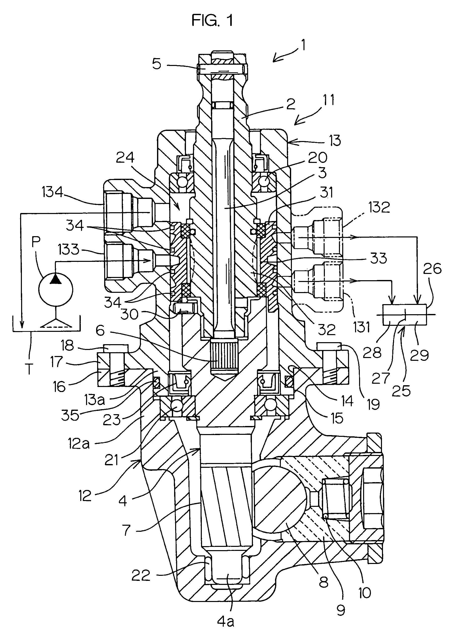
[0026]Preferred embodiments of the present invention will be described while referring to the accompanying drawings.

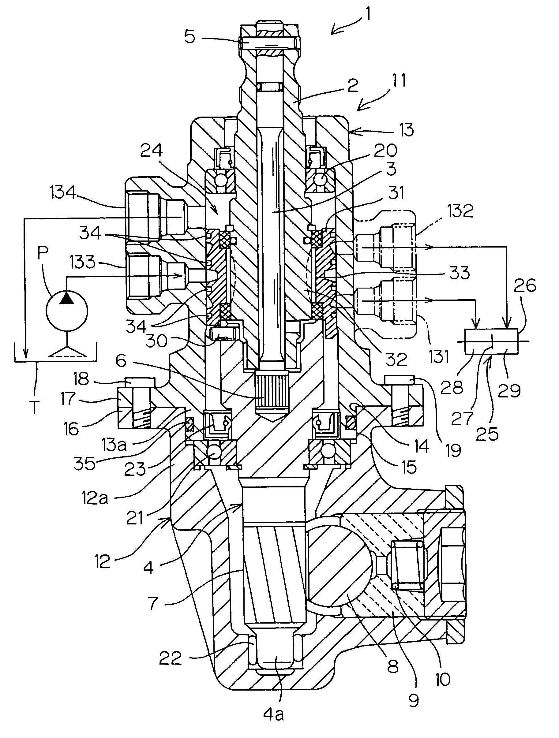
[0027]FIG. 1 is a schematic sectional view of a steering apparatus according to an embodiment of the present invention. Referring to FIG. 1, a rack-and-pinion hydraulic power steering apparatus 1 (hereinafter merely referred to as a steering apparatus 1) comprises an input shaft 2 connected to a steering member, and an output shaft 4 (a pinion shaft) connected to the input shaft 2 through a torsion bar 3. The torsion bar 3 is connected to the input shaft 2 through a pin 5 serving as a connecting member, and is connected to the output shaft 4 through a serration 6. Consequently, the input shaft 2 and the output shaft 4 elastically rotate relative to each other in response to steering torque.

[0028]A pinion 7 is formed integrally with the outer periphery of the output shaft 4 so as to concentrically rotate, and a rack shaft 8 meshed with the pinion 7 is connected to a whe...


PUM


Abstract

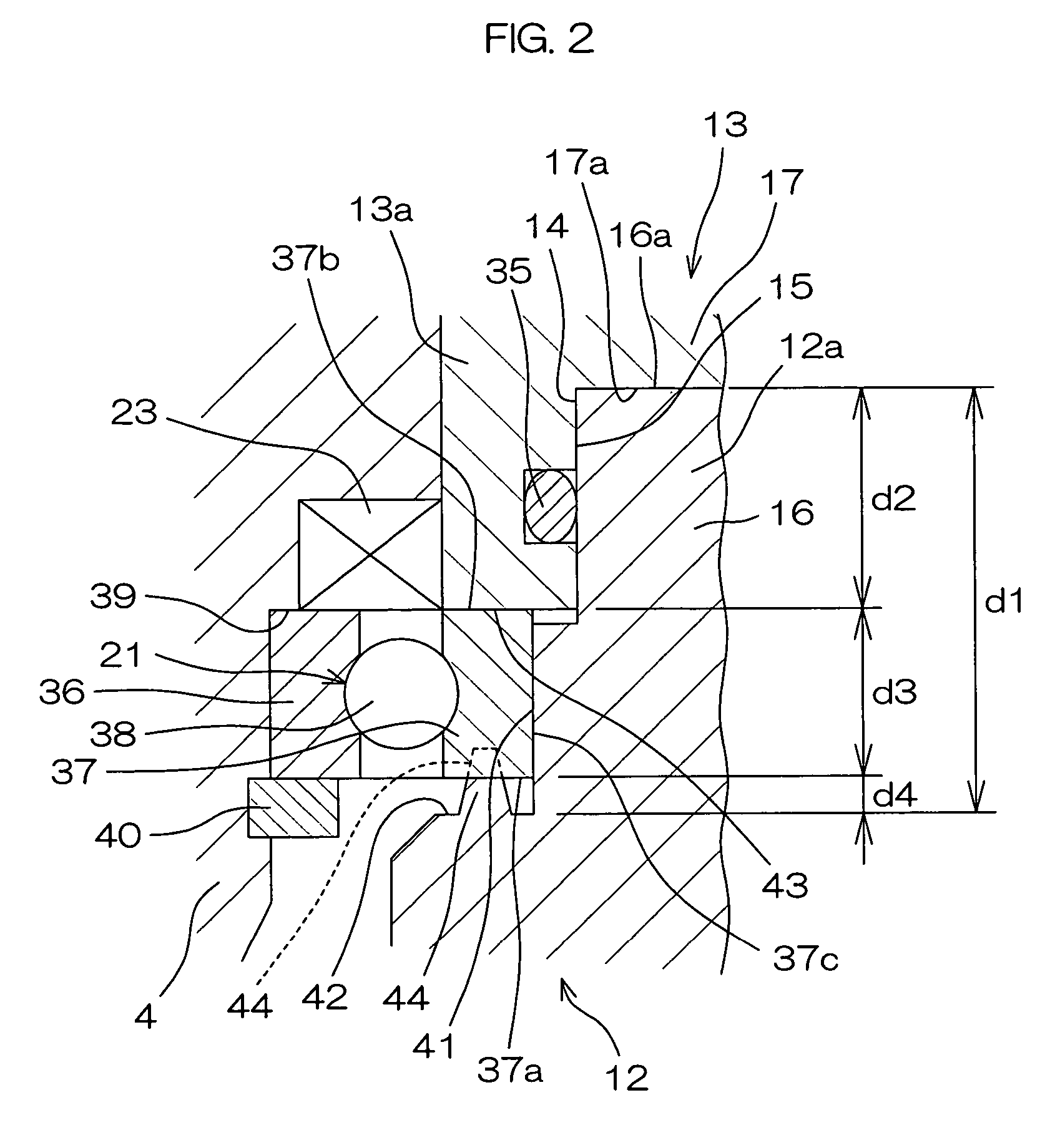
A steering apparatus comprises a bearing for supporting a pinion shaft so as to be rotatable and a high-rigidity member for holding the bearing in a state where it is positioned with respect to a housing. The housing comprises cylindrical first and second housings whose respective ends are fitted to each other. The first and second housings respectively comprise first and second receiving sections directly or indirectly receiving an outer ring of the bearing in an axial direction. The outer ring of the bearing is held between the high-rigidity member and the second receiving section, so that the axial movement of the bearing relative to the first and second housings is regulated.

Description

BACKGROUND OF THE INVENTION[0001]1. Field of the Invention[0002]The present invention relates to a rack-and-pinion steering apparatus having a so-called drop-in structure.[0003]2. Description of Related Art[0004]In a rack-and-pinion hydraulic power steering apparatus having a drop-in structure, for example, a valve housing for accommodating a hydraulic control valve incorporates the hydraulic control valve and a pinion shaft serving as an output shaft, to form a sub-assembly. The pinion shaft in the sub-assembly is then inserted into (dropped into) a pinion housing. The valve housing and the pinion housing are then connected to each other, to complete assembling work.[0005]An outer ring in a bearing for supporting the pinion shaft is held along the axis of the pinion shaft between receiving sections respectively provided in the valve housing and the pinion housing. When the distance between the receiving sections is larger than the size in the axial direction of the outer ring, a cl...

Claims


Application Information

Patent Timeline
Patent Type & Authority Patents(United States)
IPC IPC(8): F16H35/00
CPCB62D3/12Y10T74/1967F16C35/067
Inventor KOJIMA, TAKAHIROHAMANO, MASAOTAKADA, NOBUSHIGETOSHIMA, AKIHIRO
Owner JTEKT CORP
Learn More