LED lamp with a heat dissipation device

a technology of heat dissipation device and led lamp, which is applied in the direction of lighting and heating apparatus, semiconductor devices for light sources, and support devices for lighting and heating apparatus. it can solve the problems of instability of the operation of conventional led modules, rapid rise in temperature of led modules, and increased heat generated by led modules

Inactive Publication Date: 2010-08-03
FU ZHUN PRECISION IND SHENZHEN +1
View PDF7 Cites 44 Cited by
  • Summary
  • Abstract
  • Description
  • Claims
  • Application Information

AI Technical Summary

Benefits of technology

[0005]LED modules for use in an LED lamp require many LEDs, and most of the LEDs are driven at the same time, which results in a quick rise in temperature of the LED modules. Therefore, a heat dissipation device is needed to dissipate heat generated by the LED modules of the LED lamp. A related heat dissipation device attached to the LED modules usually comprises a heat sink having a base and a plurality of fins mounted on one side of the base. The LED modules are mounted on another side of the base opposite to the fins. The fins are located parallel to each other and perpendicular to the base. A plurality of channels are defined between the fins of the heat sink and arranged parallel to each other. A cooling airflow passes through the channels defined by the fins of the heat sink, whereby heat generated by the LED modules can be absorbed by the fins and then dissipated to atmosphere. Accordingly, the LED lamp can be cooled to some degree.

Problems solved by technology

LED modules for use in an LED lamp require many LEDs, and most of the LEDs are driven at the same time, which results in a quick rise in temperature of the LED modules.
However, as a power of the LED modules for use in the LED lamp continues to advance, an amount of heat generated by the LED modules becomes more and more huge.
Operation of the conventional LED modules has a problem of instability because of insufficient heat dissipating efficiency of the heat dissipation device.
Consequently, the light from the LED lamp often flickers, which degrades the quality of the illumination.
Besides, since the LED modules are generally arranged on a heat dissipation device which has a flattened surface, an illumination area of the LED lamp is restricted by the arranged position of the LED modules, whereby a larger illumination area can not be provided.

Method used


Image

  • LED lamp with a heat dissipation device
  • LED lamp with a heat dissipation device
  • LED lamp with a heat dissipation device

Examples


Embodiment Construction

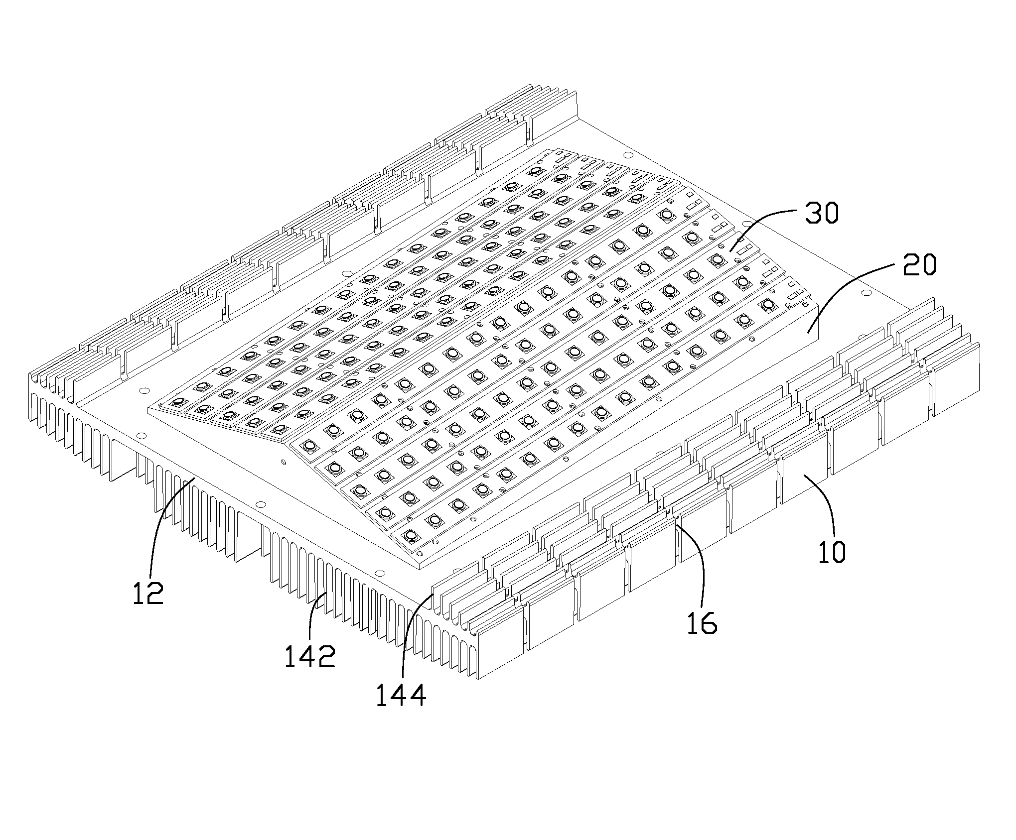
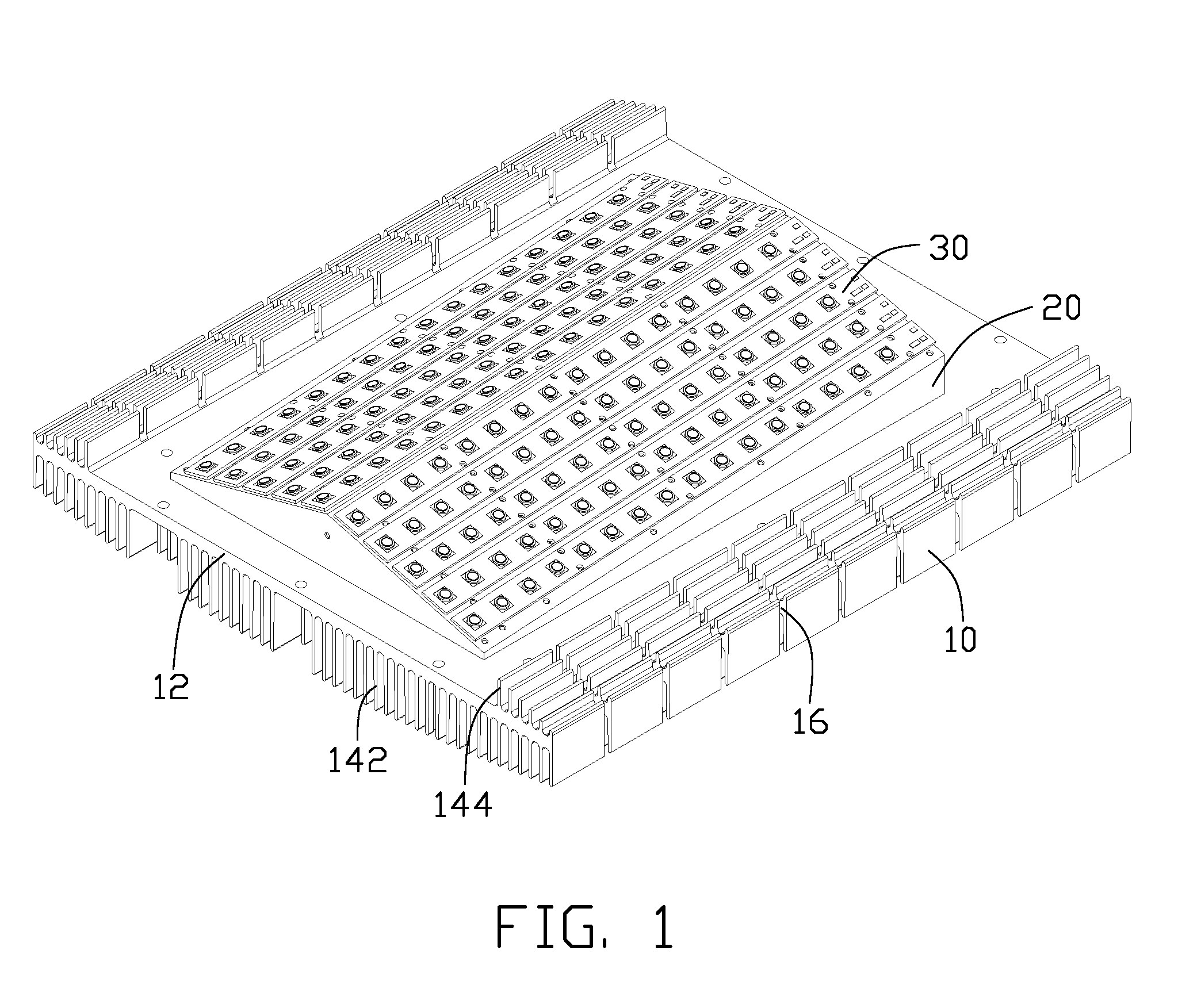
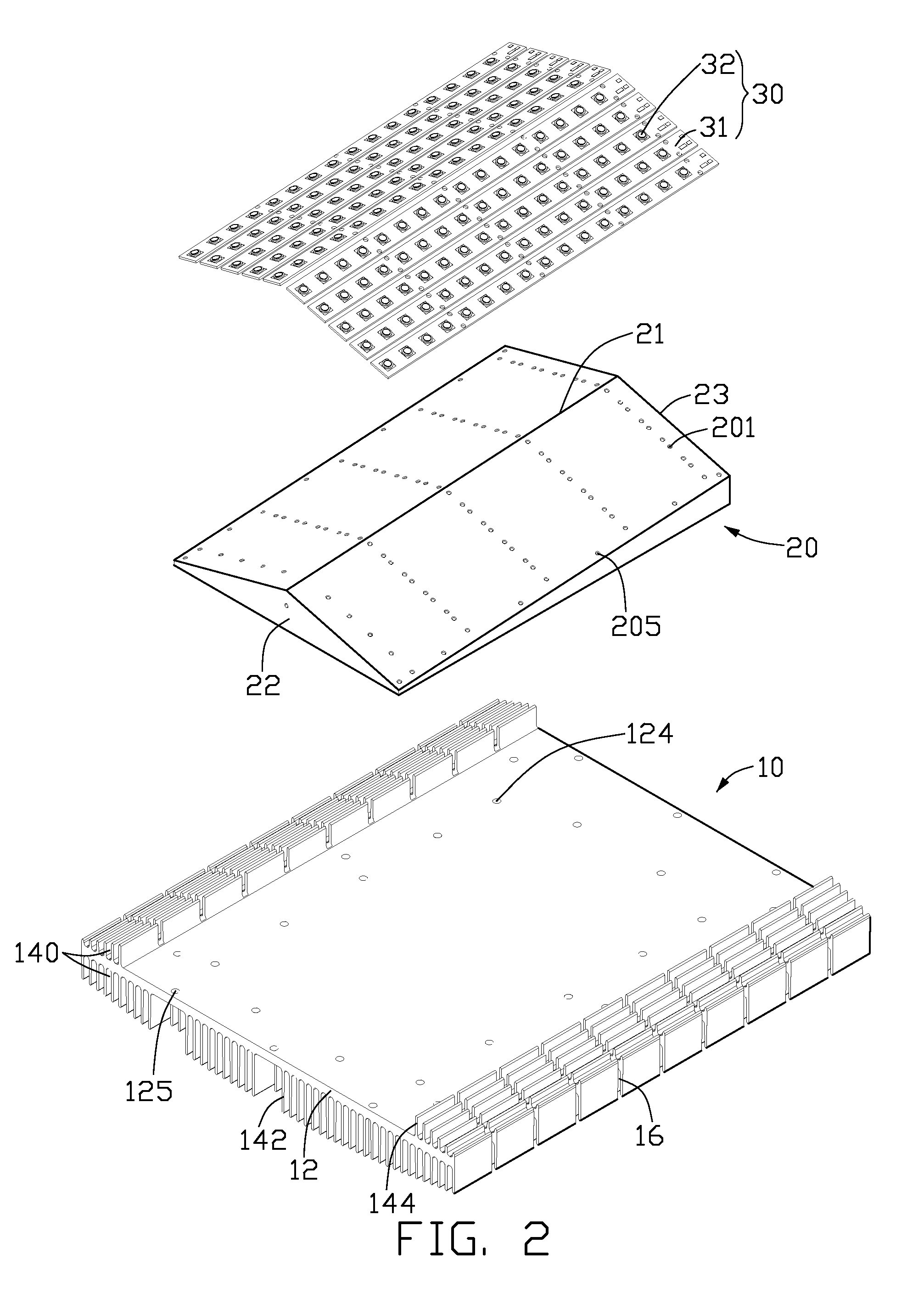
[0017]Referring to FIGS. 1-3, an LED lamp with a heat dissipation device in accordance with a preferred embodiment is illustrated. The LED lamp comprises a heat sink 10, a triangular-shaped ridge 20 positioned on the heat sink 10 and an LED module 30 attached to the ridge 20. The heat sink 10 and the ridge 20 are used to cool down the LED module 30 to keep the LED module 30 working within an acceptable temperature range.

[0018]The heat sink 10 comprises a base 12, a plurality of first fins 142 extending from a bottom surface of the base 12 and a plurality of second fins 144 extending from a top surface of the base 12. The base 12 has a substantially rectangular shape. A plurality of first through holes 124 corresponding to side edges of the ridge 20 are defined in the base 12 for fixtures (not shown) to extend therethrough to secure the ridge 20 on the base 12. A plurality of second through holes 125 are defined around the first through holes 124 for fixtures (not shown) to extend th...


PUM


Abstract

An LED lamp includes a heat sink, a triangular-shaped ridge positioned on the heat sink and an LED module mounted on the ridge. The heat sink includes a base and a plurality of first and second fins respectively extending from a first and a second surface of the base, with a plurality of channels defined between the first and second fins. The ridge is positioned on the second surface of the base. The ridge has a lateral surface which has a height decreasing from a middle to a lateral side of the ridge and decreasing from a rear end to a front end of the ridge. The LED module is mounted on the lateral surface of the ridge.

Description

BACKGROUND OF THE INVENTION[0001]1. Field of the Invention[0002]The present invention relates to a light emitting diode (LED) lamp, and more particularly to an LED lamp incorporating a heat dissipation device for improving heat dissipation of the LED lamp.[0003]2. Description of Related Art[0004]An LED lamp is a type of solid-state lighting that utilizes light-emitting diodes (LEDs) as a source of illumination. An LED is a device for transferring electricity to light by using a theory that, if a current is made to flow in a forward direction through a junction comprising two different semiconductors, electrons and cavities are coupled at the junction region to generate a light beam. The LED has an advantage that it is resistant to shock, and has an almost eternal lifetime under a specific condition; thus, the LED lamp is intended to be a cost-effective yet high quality replacement for incandescent and fluorescent lamps.[0005]LED modules for use in an LED lamp require many LEDs, and ...

Claims


Application Information

Patent Timeline
Patent Type & Authority Patents(United States)
IPC IPC(8): F21V29/00
CPCF21K9/00F21V29/004F21V29/76F21V29/75F21Y2101/02F21Y2115/10F21V29/763
Inventor ZHANG, WEN-XIANGYU, GUANGLAI, CHENG-TIEN
Owner FU ZHUN PRECISION IND SHENZHEN
Why Eureka
Try Eureka