Method of operating an infrared drip sensor in an enteral pump system to reduce false alarm conditions

a drip sensor and infrared technology, applied in the field of enteral pumps, can solve the problems of affecting the operation of the infrared drip sensor in the enteral pump system, affecting the accuracy of the infrared drip sensor,

Active Publication Date: 2010-08-03
ALCOR SCI A RHODE ISLAND
View PDF18 Cites 66 Cited by
  • Summary
  • Abstract
  • Description
  • Claims
  • Application Information

AI Technical Summary

Benefits of technology

[0010]The present invention preserves the well known advantages of prior methods of operating an infrared drip sensor in an enteral system but, in addition, provides new advantages not found in currently available methods and overcomes many disadvantages of the currently available methods for operating an infrared drip sensor.
[0013]It is therefore an object of the present invention to provide a method of operating an enteral pump with reduced occurrences of false alarms.

Problems solved by technology

False alarms are an undesirable consequence of fixed sensitivity when the transparent wall of the drip chamber may become less transparent through the accumulation of liquid residue or droplets.
These droplets are only a problem when they are located in the path of the IR beam.
This issue is more problematic for water due to its propensity for droplet formation due to its high surface tension.
Water however, has a tendency to stay in place longer and thus create a blocking condition.
With fixed infrared detector sensitivity, water droplets will cause false alarms.
In addition to the liquid nutrient, caregivers must also give water to the patient, as the liquid nutrient contains insufficient water for normal dietary requirements.
Both of these configurations are relatively high in cost because of the multiple motors.

Method used


Image

  • Method of operating an infrared drip sensor in an enteral pump system to reduce false alarm conditions
  • Method of operating an infrared drip sensor in an enteral pump system to reduce false alarm conditions
  • Method of operating an infrared drip sensor in an enteral pump system to reduce false alarm conditions

Examples


Embodiment Construction

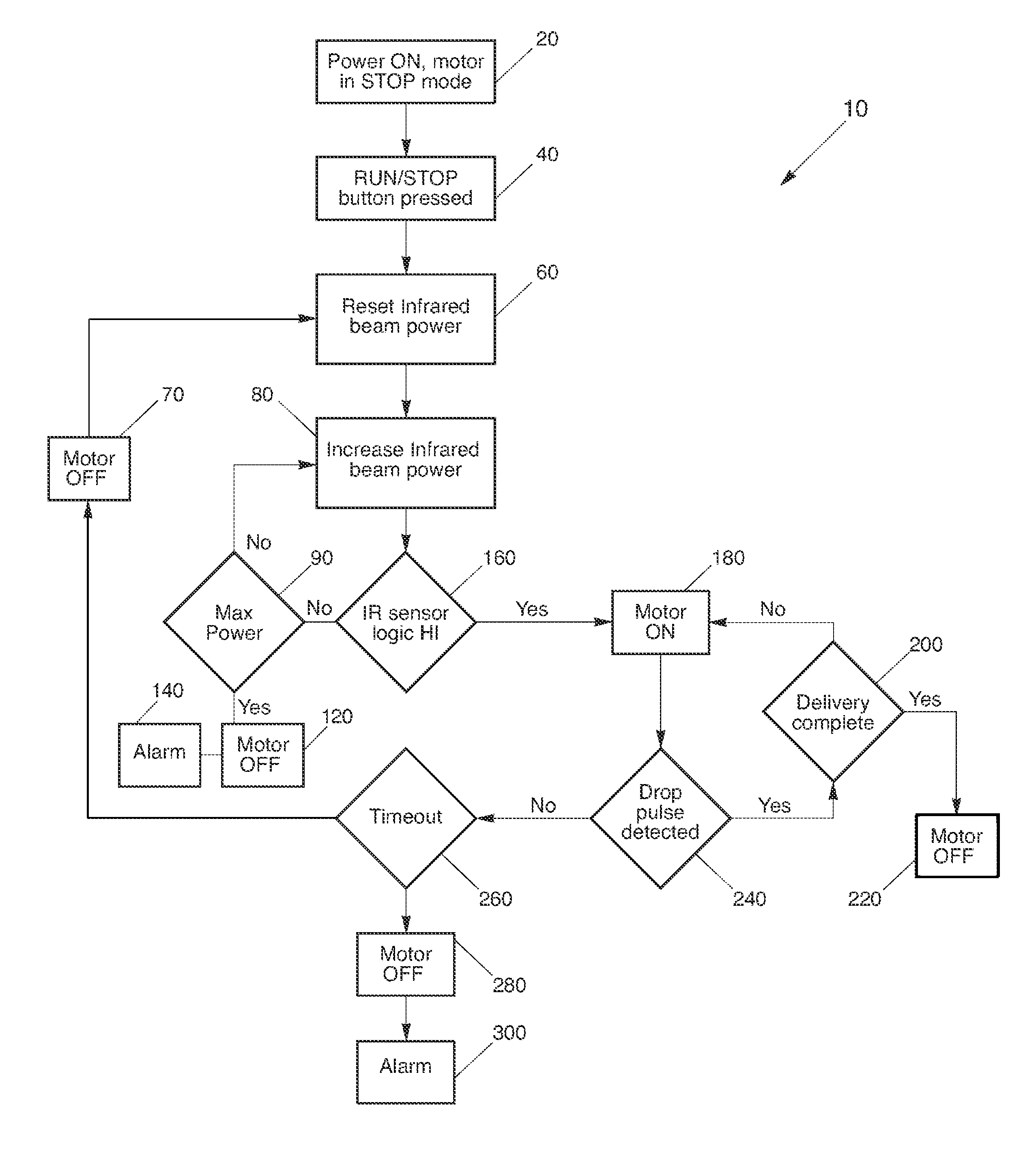
[0023]The present method solves a disadvantage of the prior art by providing a new and unique method 10 for operating a drip sensor system in an enteral pump system, which reduces false alarm conditions.

[0024]As described in the background, an enteral pumping system generally consists of a pump system 302 and disposable tubing set for delivery of the liquid nutrition. The tubing set is connected between a bag of liquid nutrition and a patient's gastric line. A section of the tubing set is seated on the pump housing where a rotor draws fluid through the tubing set by peristaltic action.

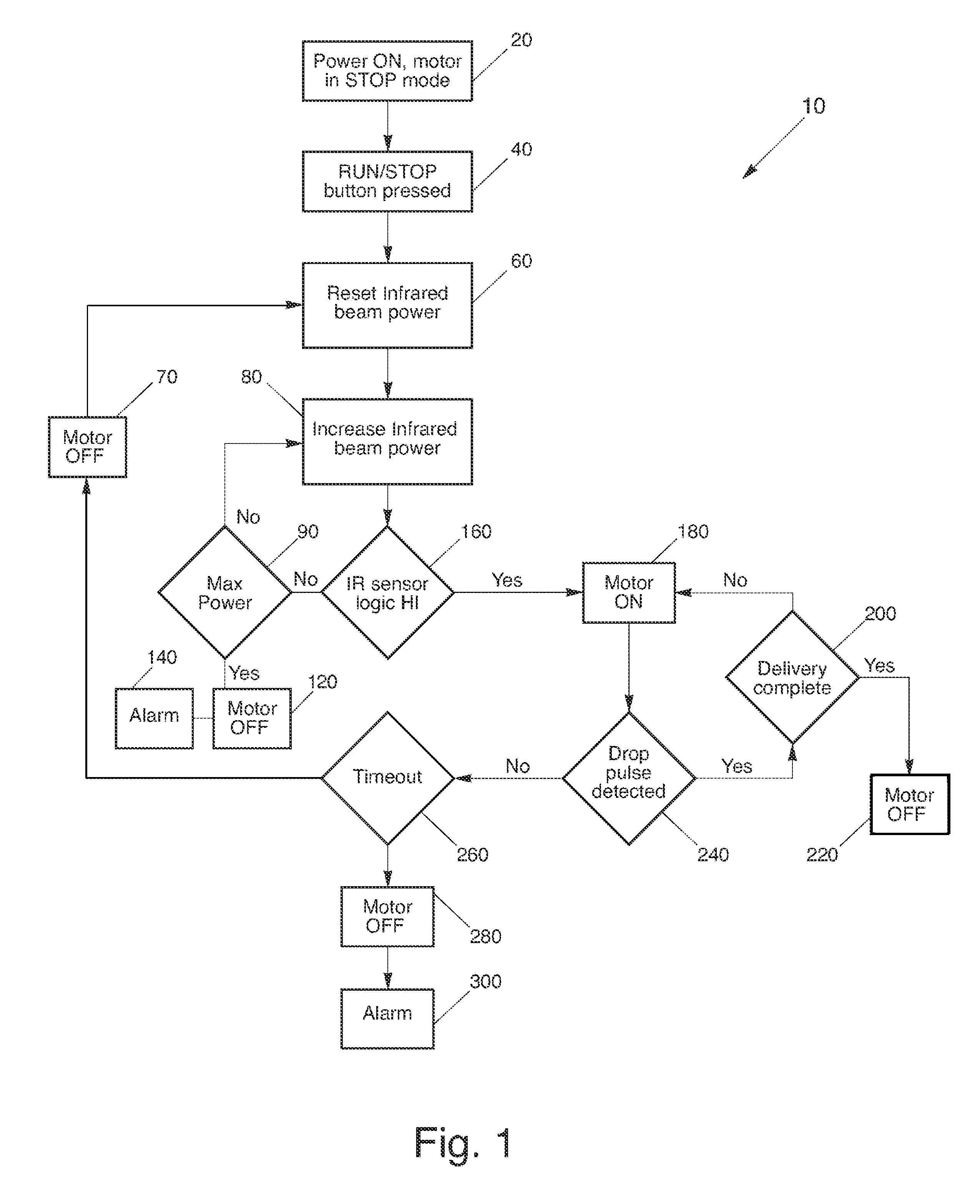
[0025]Generally, the pump system 302 comprises a controller 304, pump motor 306, power source 308, and an infrared sensor system 350 containing an infrared beam emitter 380 and infrared beam sensor 360. See FIG. 6. The controller 304 is powered by the power source 308 and controls the pump motor 306 and the infrared sensor system 305. More specifically, the controller 304 instructs the pump motor 306 w...


PUM

PropertyMeasurementUnit
power levelaaaaaaaaaa
poweraaaaaaaaaa
liquidaaaaaaaaaa

Abstract

The present invention provides a method of operating an infrared drip sensor in an enteral pump system to reduce false alarm conditions. The method consists of the following steps: optically coupling a infrared beam emitter with an infrared beam detector along an infrared beam path that extends through a drip chamber and intersects the drip path; monitoring the output signal of the infrared beam detector to detect pulses; monitoring the pulses for an interruption thereof; and running an infrared beam power update routine when an interruption is detected in the pulses, the infrared beam power update routine consisting of incrementally increasing a power level of the infrared beam until the power level of the infrared beam is sufficient to re-establish an output signal at the infrared beam detector.

Description

CROSS-REFERENCE TO RELATED APPLICATION[0001]This application is related to and claims priority from earlier filed provisional patent application Ser. No. 60 / 869,386, filed Dec. 11, 2006.BACKGROUND OF THE INVENTION[0002]The present invention relates to enteral pumps for delivering liquid nutrition to patients who are unable to eat.[0003]Enteral feeding pumps are used to supply liquid nutrition to patients who are unable to eat. The pumping system generally consists of the pump and a disposable tubing set for delivery of the liquid nutrition. The tubing set is connected between a bag of liquid nutrition and a patient's gastric line. A section of the tubing set is seated on the pump housing where a rotor draws fluid through the tubing set by peristaltic action.[0004]A common design feature of enteral pumps is the ability to detect the presence or absence of liquid flowing through the tube set. This is typically accomplished by the detection of drops falling within a transparent drip ch...

Claims


Application Information

Patent Timeline
Patent Type & Authority Patents(United States)
IPC IPC(8): G01N15/06
CPCA61M5/1689
Inventor SACCHETTI, PETER J.
Owner ALCOR SCI A RHODE ISLAND
Why Eureka
Try Eureka