Handguard system with clamp device

a technology of clamping device and handguard, which is applied in the field of handguards, can solve the problems of temporary disablement of weapons, adversely affecting accuracy, impracticality or impossible, etc., and achieve the effect of preventing handguard misalignmen

Inactive Publication Date: 2010-08-10
TANKERSLEY JEROME BENEDICT
View PDF20 Cites 113 Cited by
  • Summary
  • Abstract
  • Description
  • Claims
  • Application Information

AI Technical Summary

Benefits of technology

[0045]In another example, the handguard system clamp device is spring loaded. The spring is interposed between the actuating screw and the clamp pad. The spring maintains gripping force and prevents handguard misalignment caused by parts wear and extreme temperature variations, with minimal need for user intervention.
[0046]In a more detailed example, the handguard system, in addition to having a barrel nut, handguard, and clamp device, further includes an improved or low profile-integral rail gas block attached to the

Problems solved by technology

These handguards contact the barrel at one or more locations and may conduct external forces to the barrel, adversely affecting accuracy.
This can be impractical or impossible, particularly in a battle zone.
They have the advantage that the weapon does not have to be fired to obtain zero, but the disadvantage that the weapon is temporarily disabled during this process as the bore is blocked by the boresight.
Also, these laser boresights don't mount to a standard dovetail rail, making them single purpose devices.
In this regard, prior art gas blocks, particularly large configuration integral front sight and integral rail blocks, affixed to the barrel, have been an impediment to developing a rapidly installed and removed handguard.
Handguard systems which install longitudinally by sliding over the firearm barrel and engaging an unthreaded barrel nut outer surface have the potential for quick change or rapid installation and removal.
1. Screws bearing on metal surfaces, such as the aluminum, steel and composite materials often employed for the manufacture

Method used


Image

  • Handguard system with clamp device
  • Handguard system with clamp device
  • Handguard system with clamp device

Examples


first embodiment

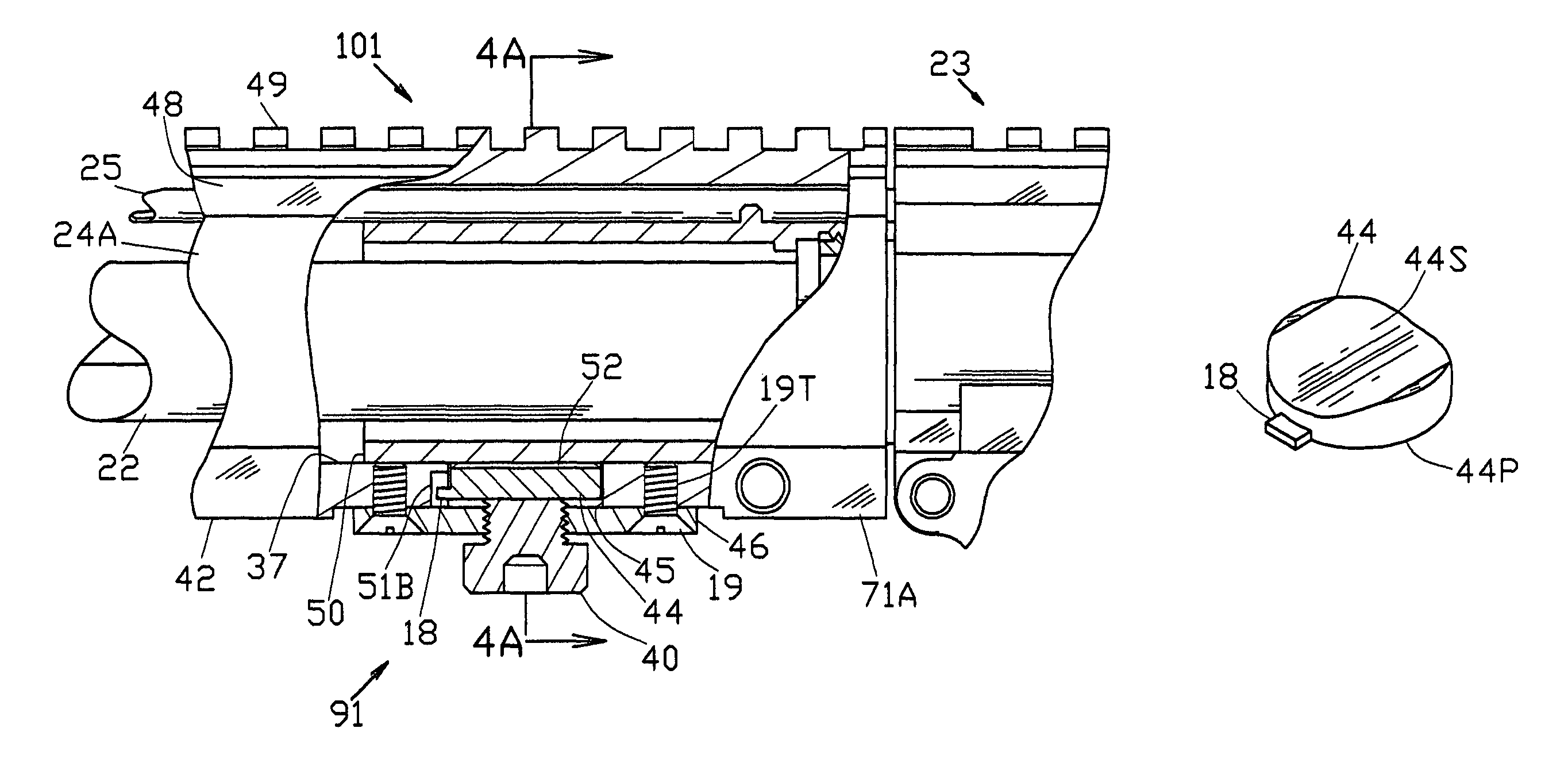
[0283]In operation, considering system embodiment 101 in FIGS. 4-4A, handguard 24A is shown engaging barrel nut 50, but clamp device 91 is in the unclamped position.

[0284]To secure handguard 24A to nut 50, actuating screw 40 is tightened and advanced in the direction of arrow A, screw end 40E contacting and moving pad 44. Gap 52 which, as an example, may measure 0.030 inch unclamped, is reduced to zero during the tightening of screw 40. After tightening of screw 40, barrel nut 50 is firmly gripped between pad 44 and the opposing or upper part of handguard inner diameter 37 which is in contact with nut outside diameter 50D.

[0285]To ensure that nut 50 is firmly gripped, for this embodiment, screw head 40H does not contact plate 46 in the tightened position, not shown. For this simple, single stage clamping process, proper tightening, or applied torque, is user-controlled by either a torque wrench, or more often in practice, by operator “feel”. For this embodiment, the purpose of head ...

second embodiment

[0296]For system embodiment 102, the clamping process is significantly different, as described below, than that for embodiment 101. Shown in FIGS. 6-6A, handguard 24B with clamp device 92 are installed to barrel nut 50 and device 92 is in the unclamped position with gap 52 separating pad 44A from nut diameter 50D. Spring 47 is in an unloaded or free position.

[0297]To secure handguard 246 to nut 50, actuating screw 40A is advanced in the direction of arrow B and tightened. Unlike embodiment 101, this clamping process is a two-stage process. First, tightening and advancing screw 40A elevates both pad 44A and spring 47 until pad surface 44S contacts nut diameter 50D. Consequently, gap 52 which, as an example, may measure 0.030 inch unclamped, is reduced to zero, as seen in FIG. 6B.

[0298]In the second stage of clamping, continued advance of screw 40A begins to compress and load spring 47 which transmits its force to pad 44A. Unlike embodiment 101, force applied to pad 44A, during clampi...

third embodiment

[0303]FIG. 6F shows a slightly different embodiment of clamp device 92, designated as clamp device 93. Device 93 is shown in the unclamped position. Clamp device 93 is similar to device 92 but includes an actuating screw 40B. Screw 40B includes a larger head 61D, which has a locking helicoil insert 61H for receiving an adjustment screw 61. The axis of insert 61H is parallel to the axis of actuating screw 40B. Screw 61 can be adjusted in the directions shown by arrow S to protrude from head 61D as desired.

[0304]When actuating screw 40B is tightened in the direction of arrow C, as when securing handguard 24B to barrel nut 50, adjustment screw 61, depending on its adjustment, contacts plate 46, thus limiting the travel of actuating screw 40B, thus limiting the deflection and force applied by spring 47 to pad 44A. Locking helicoil insert 61H locks adjustment screw 61 at the desired setting. Consequently, the gripping force that clamp device 93 applies to barrel nut 50 can controlled by ...


PUM


Abstract

In one embodiment, a handguard system with clamp device for use on a firearm. The firearm has a barrel, an operating member and a receiver. The barrel and operating member are joined to the receiver. The handguard system includes a barrel nut, a tubular handguard, a clamp device, and a low profile rail gas block. The barrel nut secures the barrel to the receiver and has an outer surface which lies inward of the operating member and engages the inner surface of the handguard. The handguard inner surface includes a groove for providing clearance to the operating member and gas block. The clamp device attaches to the handguard and includes an actuating screw and a spring loaded clamp pad which engages the barrel nut outer surface. The low profile rail gas block permits both interfacing accessories and rapid installation and removal of the handguard.

Description

CROSS-REFERENCE TO RELATED APPLICATIONS[0001]PPA 60 / 734,193 and Ser. No. 11 / 593,439 and Ser. No. 11 / 975,881FEDERALLY SPONSORED RESEARCH[0002]NoneSEQUENCE LISTING[0003]NoneFIELD OF THE INVENTION[0004]This invention relates to handguards, and more particularly to floating handguard systems which interface accessories to M16 style firearms.BACKGROUND OF THE INVENTIONPrior Art[0005]The M16 rifle is a gas operated rifle adopted by the United States armed forces during the period 1962-63. Many variations have been produced since that time including civilian models for sporting uses.[0006]The group of firearms generally considered “M16 style” includes gas operated rifles, and carbines with common design features including a barrel which attaches to the receiver with a barrel nut, a gas block, and an operating member such as a pushrod or gas tube which are part of the firearm operating mechanism.[0007]Since the initial M16 development work, including U.S. Pat. No. 2,951,424 and U.S. Pat. No...

Claims


Application Information

Patent Timeline
IPC IPC(8): F41C23/16
CPCF41C23/16
Inventor TANKERSLEY, JEROME BENEDICT
Owner TANKERSLEY JEROME BENEDICT
Why Eureka
Try Eureka