Method, apparatus, and article for force feedback based on tension control and tracking through cables

a technology of tension control and force feedback, applied in the field ofhaptic systems employing force feedback, can solve the problems of difficult control of force output, computationally expensive conversion of encoder data, and hard back of the motor

Inactive Publication Date: 2011-02-01
MIMIC TECH
View PDF24 Cites 37 Cited by
  • Summary
  • Abstract
  • Description
  • Claims
  • Application Information

AI Technical Summary

Benefits of technology

In yet another aspect, a new calibration system is provided, for maintaining tool position accuracy with minimal user intervention, even after powering down and reactivation of the apparatus over multiple iterations.
In a further aspect, an input / output haptic interface provides a user with the “touch” sensation generated as a result of interaction with virtual environments, which could include force effects such as contact force resulting from tool collision with rigid or deformable virtual surfaces, the pull, push, weight or vibration of a virtual object contacting a tool(s), and / or viscous resistance and inertia experienced as a tool moves through virtual fluid.

Problems solved by technology

The farther the user penetrates the wall, the harder the motors push back to force the joystick back to the wall surface.
Because it is computationally expensive to convert encoder data to end effecter position and translate motor torques into directional forces, a haptic device will often have its own dedicated processor.
Not only is it difficult to control force output because of the update demand, the mass of a robotic arm introduces inertial forces that must be accounted for.
Motors are used to create tension in the cables, which results in an applied force at the grip.
The “3 dimensional input device” introduced in U.S. Pat. No. 5,305,429 is not capable of controlling or rendering directional forces.
It is therefore not possible to render three-dimensional forces in the manner typically associated with a haptic device.
In other words, this device is not capable of simulating haptic effects such as the feel or contact with a virtual three-dimensional surface.
The “3 dimensional input device” cannot render controlled vector forces because of the following reasons, (i) it is impossible to display exact directional force, because the device can only apply drag, or resistance to movement to each string by ON / OFF magnetic switches and cannot impose an exact tension in each string; (ii) there is no accounting for the changing force applied by the weights attached to each string which provide a variable tension as the velocity of the moving weight changes the tension; (iii) there is no accounting for extraneous forces resulting from friction between the frame, pulleys, ON / OFF magnetic switches and the strings; and (iv) there is no initialization sequence described which is required for determining initial string lengths as need for determining string orientations and finger position so that forces can be reflected accurately.
As an input device, the system also lacks a robust measurement method for determining the length of the strings, which results in substantial fingertip position measurement errors.
There is also no means for measuring orientation of the finger (roll, pitch and yaw).
However, the above-mentioned “3 Dimensional interface device” requires at least seven strings to determine position and render force, even if rotation and grip forces are not being applied, and, while the design described above is adequate for displaying seven degrees of force feedback, there are severe limitations imposed if less than seven degrees of force feedback are required.

Method used


Image

  • Method, apparatus, and article for force feedback based on tension control and tracking through cables
  • Method, apparatus, and article for force feedback based on tension control and tracking through cables
  • Method, apparatus, and article for force feedback based on tension control and tracking through cables

Examples


Embodiment Construction

While the system described in Japanese patent 2001-282448, and outlined in the background section of this document, provides significant advantages over the previous art, there are still some problems that remain unaddressed. For example, when calculating the length of each string, error is introduced because a changing spool diameter resulting from string wrapped over itself on the spool is not accounted for; the device calculates rotation based on the length change in eight strings, where a minor error in length variation of one string can substantially affect accuracy (calculation algorithm is not robust about rotation); there is no initialization sequence provided, which is necessary for determining initial string length as required for determining position, orientation and grip, and minimizing associated error; the grip is connected with eight strings, so workspace is limited if the user wishes to avoid tangling the strings; and there is no accounting for extraneous forces resu...


PUM


Abstract

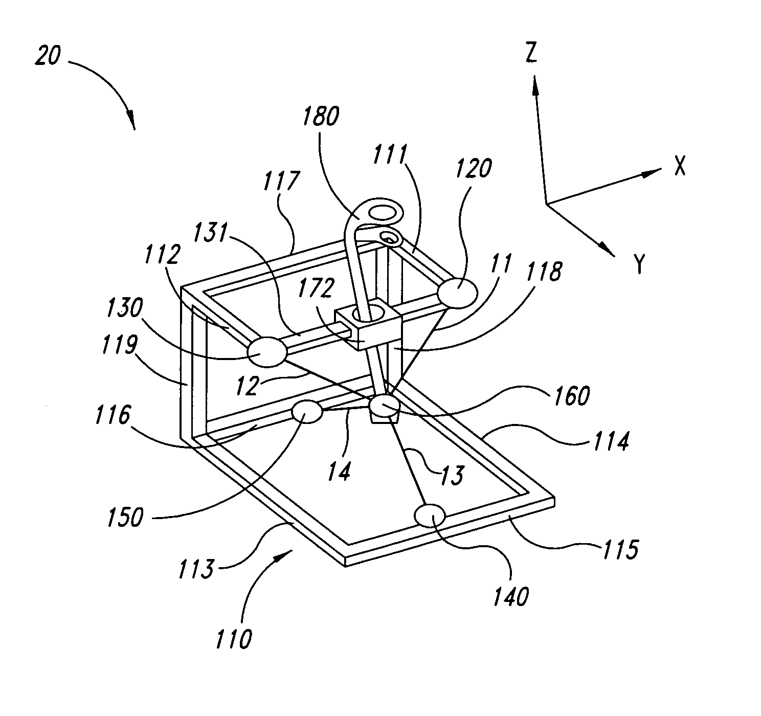
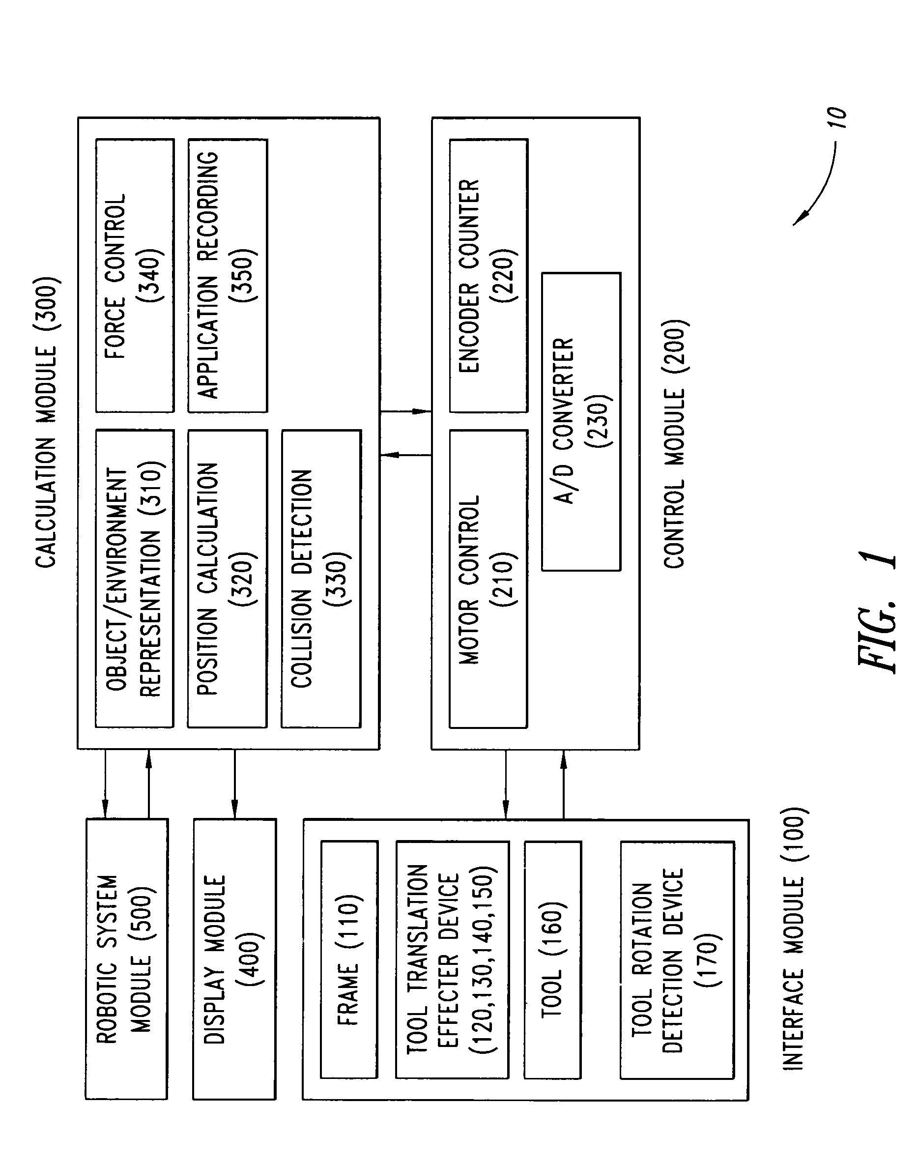
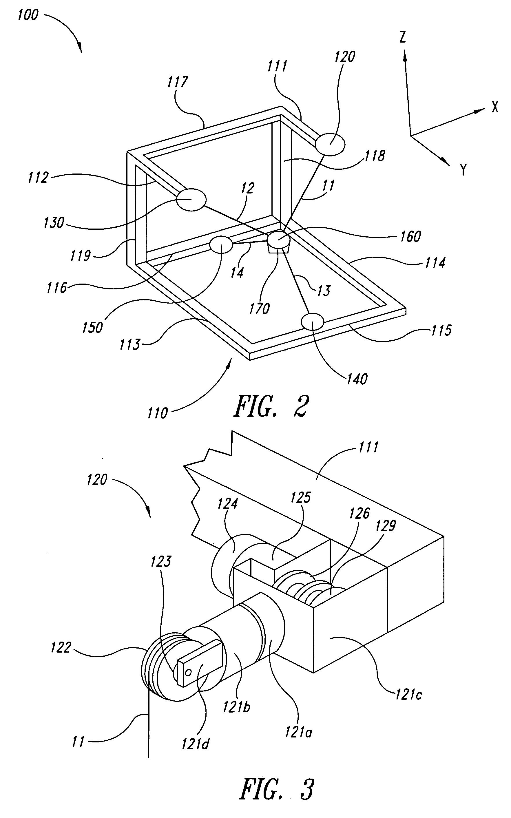
A haptic device for human / computer interface includes a user interface tool coupled via cables to first, second, third, and fourth cable control units, each positioned at a vertex of a tetrahedron. Each of the cable control units includes a spool and an encoder configured to provide a signal corresponding to rotation of the respective spool. The cables are wound onto the spool of a respective one of the cable control units. The encoders provide signals corresponding to rotation of the respective spools to track the length of each cable. As the cables wind onto the spools, variations in spool diameter are compensated for. The absolute length of each cable is determined during initialization by retracting each cable In turn to a zero length position. A sensor array coupled to the tool detects rotation around one or more axes.

Description

BACKGROUND OF THE INVENTION1. Field of the InventionThe disclosure is generally related to haptic systems employing force feedback.2. Description of the Related ArtTouch, or haptic interaction is a fundamental way in which people perceive and effect change in the world around them. Our very understanding of the physics and geometry of the world begins by touching and physically interacting with objects in our environment. The human hand is a versatile organ that is able to press, grasp, squeeze or stroke objects; it can explore object properties such as surface texture, shape and softness; and it can manipulate tools such as a pen or wrench. Moreover, touch interaction differs fundamentally from all other sensory modalities in that it is intrinsically bilateral. We exchange energy between the physical world and ourselves as we push on it and it pushes back. Our ability to paint, sculpt and play musical instruments, among other things depends on physically performing the task and lea...

Claims


Application Information

Patent Timeline
Patent Type & Authority Patents(United States)
IPC IPC(8): G05B11/01G05B15/00G06F19/00A61B5/103G06G7/48G09G5/00B25J15/00B25J15/02B25J15/08F16D31/02G06FG06F3/01G06F3/038G09G5/08
CPCG06F3/016G06F3/038G06F3/04815G06F3/0338A61B2019/2242G06F2203/015A61B34/71
Inventor BERKLEY, JEFFREY J.KIM, SEAHAKHONG, SUNGKWAN
Owner MIMIC TECH
Why Eureka
Try Eureka