Liquid cooled hybrid

a hybrid and liquid cooling technology, applied in the direction of vehicles, pedestrian/occupant safety arrangements, weapons, etc., can solve the problems of increasing affecting the efficiency of the inflator, and the high cost of the filter, so as to reduce the amount of gas generant necessary to produce sufficient inflation gas, increase the gas within the chamber, and reduce the size and cost of the inflator

Inactive Publication Date: 2010-08-10
AUTOLIV ASP INC
View PDF10 Cites 23 Cited by
  • Summary
  • Abstract
  • Description
  • Claims
  • Application Information

AI Technical Summary

Benefits of technology

[0014]When the liquid contacts the gas, at least some of the liquid is vaporized into a gas stream. Obviously, this vaporization process is endothermic and operates to cool the gas. Thus, by using a system that has evaporating liquid, the inflation gas may be cooled without the use of an expensive filter. Further, this vaporization of the liquid increases the amount of gas within the chamber. Thus, by using the liquid, the amount of gas generant necessary to produce sufficient inflation gas is reduced, further reducing the size and cost of the inflator.
[0016]It should also be noted that the present embodiments do not necessarily have to be filterless. A filter may also be used. However, the system may be “partially” filterless as the size and type of the filter needed may be reduced.

Problems solved by technology

However, the filter is often expensive and adds significant cost and weight to the inflator.

Method used


Image

  • Liquid cooled hybrid
  • Liquid cooled hybrid
  • Liquid cooled hybrid

Examples


Embodiment Construction

[0031]The presently preferred embodiments of the present invention will be best understood by reference to the drawings, wherein like parts are designated by like numerals throughout. It will be readily understood that the components of the present invention, as generally described and illustrated in the figures herein, could be arranged and designed in a wide variety of different configurations. Thus, the following more detailed description of the present embodiments, as represented in the Figures, is not intended to limit the scope of the invention, as claimed, but is merely representative of presently preferred embodiments of the invention.

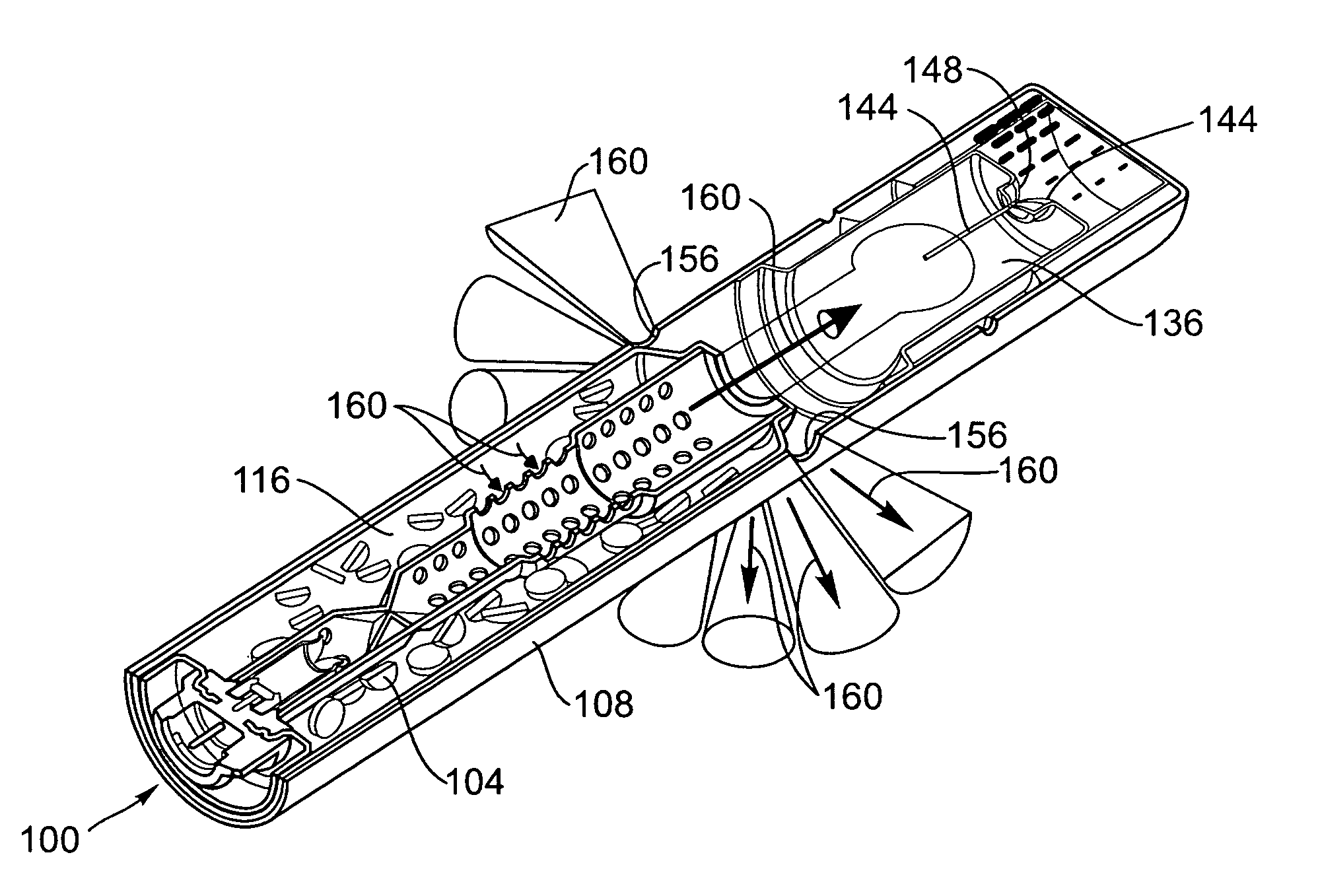
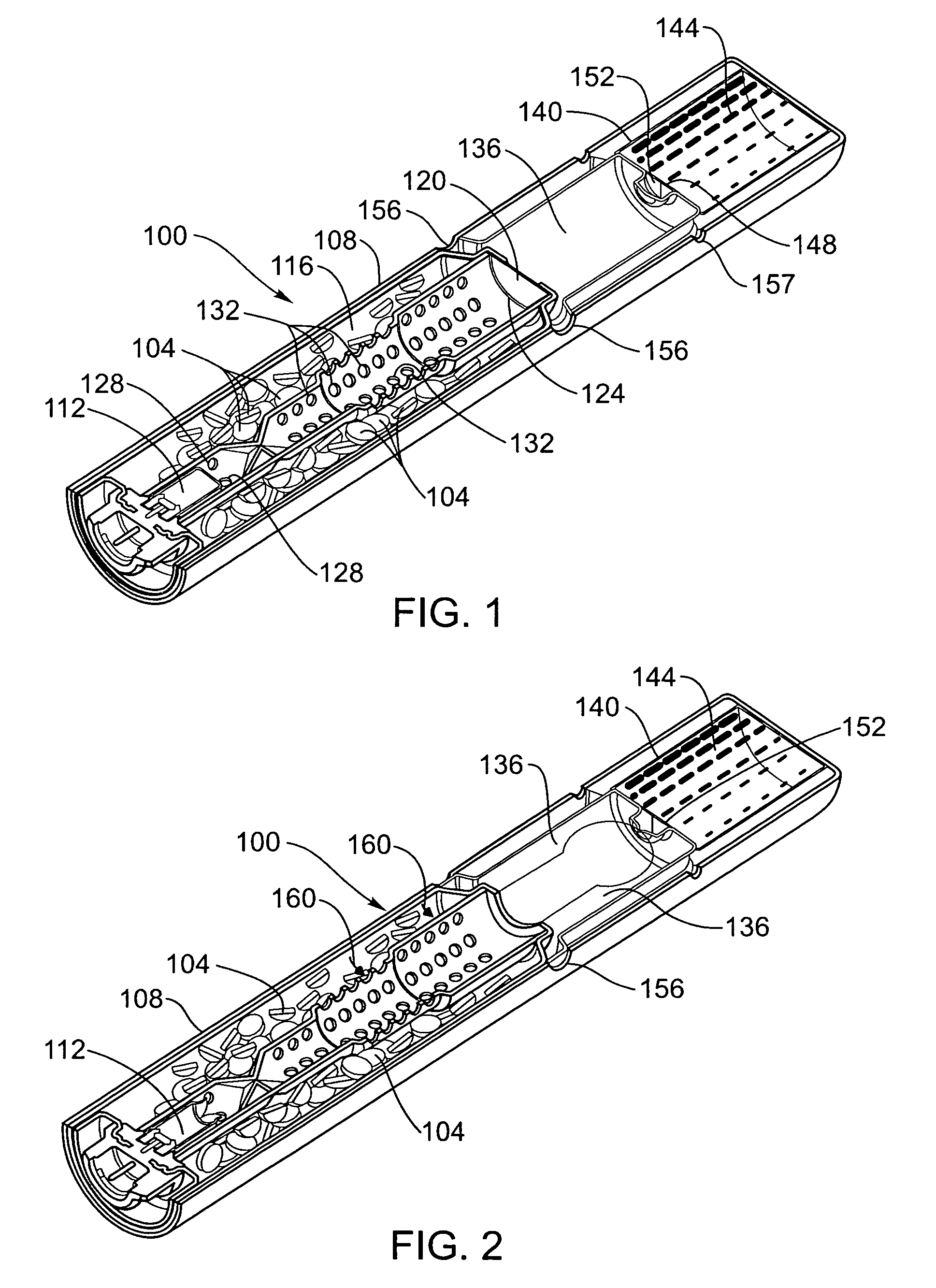
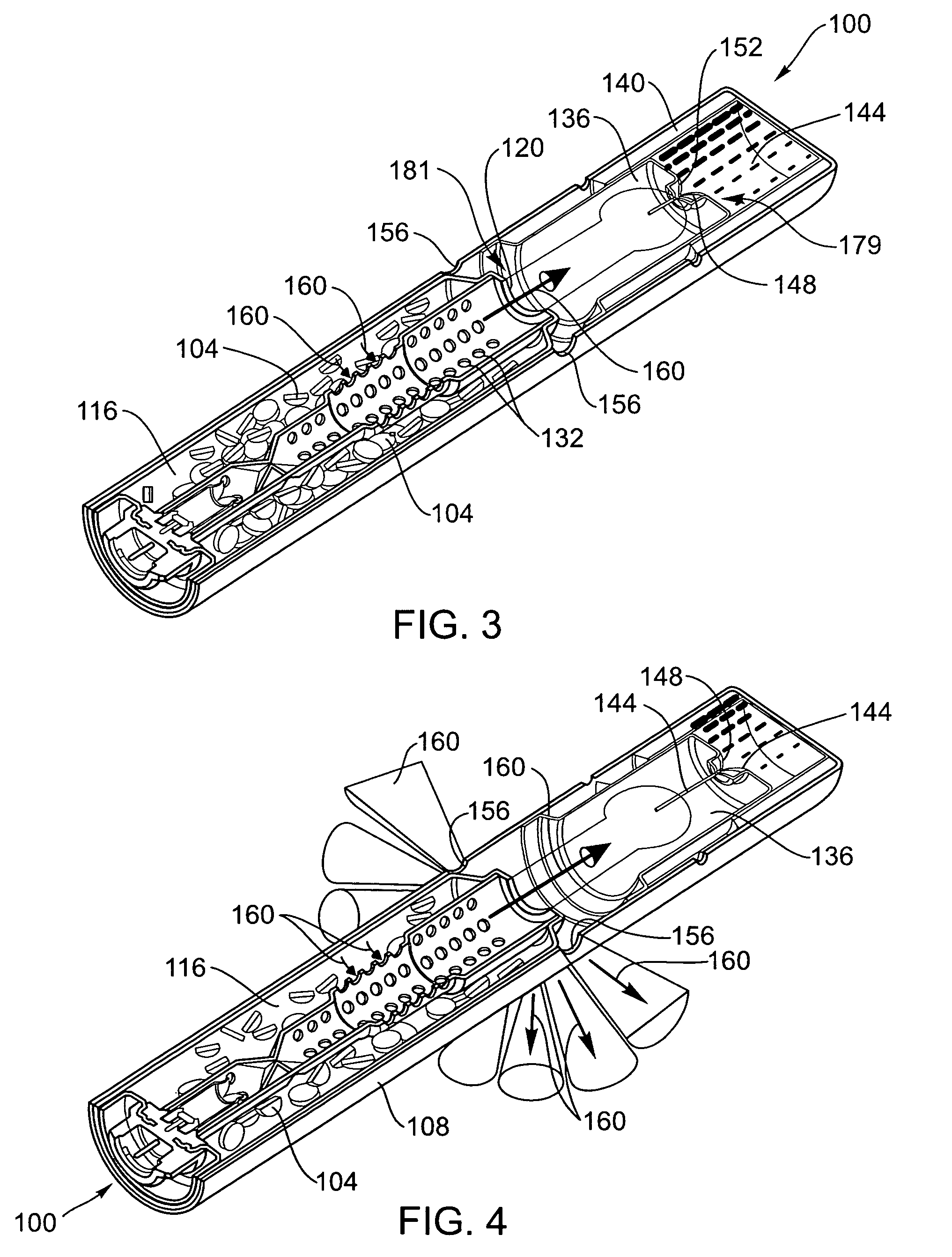
[0032]Referring now to FIG. 1, a sectional view of an inflator 100 is illustrated. The inflator includes a quantity of gas generant 104 housed within a housing 108. An initiator 112 is also added to the inflator 100. The initiator 112 is used to ignite the gas generant 104. When the gas generant 104 is ignited, a quantity of inflation gas is fo...


PUM


Abstract

An inflator that includes a quantity of gas generant housed within a chamber. A liquid and a piston are also housed within another chamber. This chamber is sealed by a burst disk. The piston includes an opening. During deployment of the inflator, the burst disk is ruptured and the piston moves towards the distal end of the inflator. The movement of the piston hydraulically expels the liquid through the opening in the piston such that the liquid cools and contacts the gas formed by combustion of the gas generant.

Description

BACKGROUND OF THE INVENTION[0001]Airbags and airbag systems have been known and used for decades and have been credited with saving many lives and preventing many injuries. Airbag systems are used to deploy an airbag during a crash into a vehicle interior so that the vehicle occupant will impact the deployed airbag rather than the harder surface(s) of the vehicle interior.[0002]Airbag systems generally include an inflator. An inflator is a device that is designed to produce and / or channel a quantity of inflation gas into the airbag during the deployment process. This influx of gas into the airbag inflates and deploys the airbag into the proper position. A variety of different inflators are known in the industry.[0003]One type of known inflator is the so-called “pyrotechnic” inflator. Pyrotechnic inflators include a quantity of gas generant that is combusted to produce the inflation gas necessary to deploy the airbag. Accordingly, pyrotechnic inflators generally include the quantity ...

Claims


Application Information

Patent Timeline
Patent Type & Authority Patents(United States)
IPC IPC(8): B60R21/264
CPCB60R21/264B60R2021/26017B60R21/2644
Inventor COX, MATTHEW A.SMITH, BRADLEY W.PARKINSON, DAVID W.PARKS, BRENT A.
Owner AUTOLIV ASP INC
Why Eureka
Try Eureka