Cambered vane for use in turbochargers

a turbocharger and camber vane technology, applied in the field of camber vanes for turbochargers, can solve the problems of not contributing to the most efficient turbocharger operation, and achieve the effect of increasing the effective operating range of the turbocharger and improving the gas flow distribution

Inactive Publication Date: 2010-08-10
HONEYWELL INT INC
View PDF2 Cites 26 Cited by
  • Summary
  • Abstract
  • Description
  • Claims
  • Application Information

AI Technical Summary

Benefits of technology

[0009]Vanes configured in this manner provide improved gas flow distribution within the turbine housing, thereby operating to increasing the effective operating range of the turbocharger.

Problems solved by technology

However, such straight vanes are only able to provide a well-distributed flow of exhaust gas to the turbine wheel within a small range of the total use, thereby not contributing to the most efficient turbocharger operation.

Method used


Image

  • Cambered vane for use in turbochargers
  • Cambered vane for use in turbochargers
  • Cambered vane for use in turbochargers

Examples


Embodiment Construction

[0018]The invention, constructed in accordance with the principles of this invention, comprises a cambered vane for use in a vaned turbocharger, including but not limited to a variable geometry turbocharger (VGT). For convenience, an exemplary embodiment using a VGT will be described throughout this specification. However, it will be readily understood by those skilled in the relevant technical field that the improved vane of the present invention could be used in a variety of turbocharger configurations, including fixed vane turbochargers and those of the sliding and / or pivoting vane type.

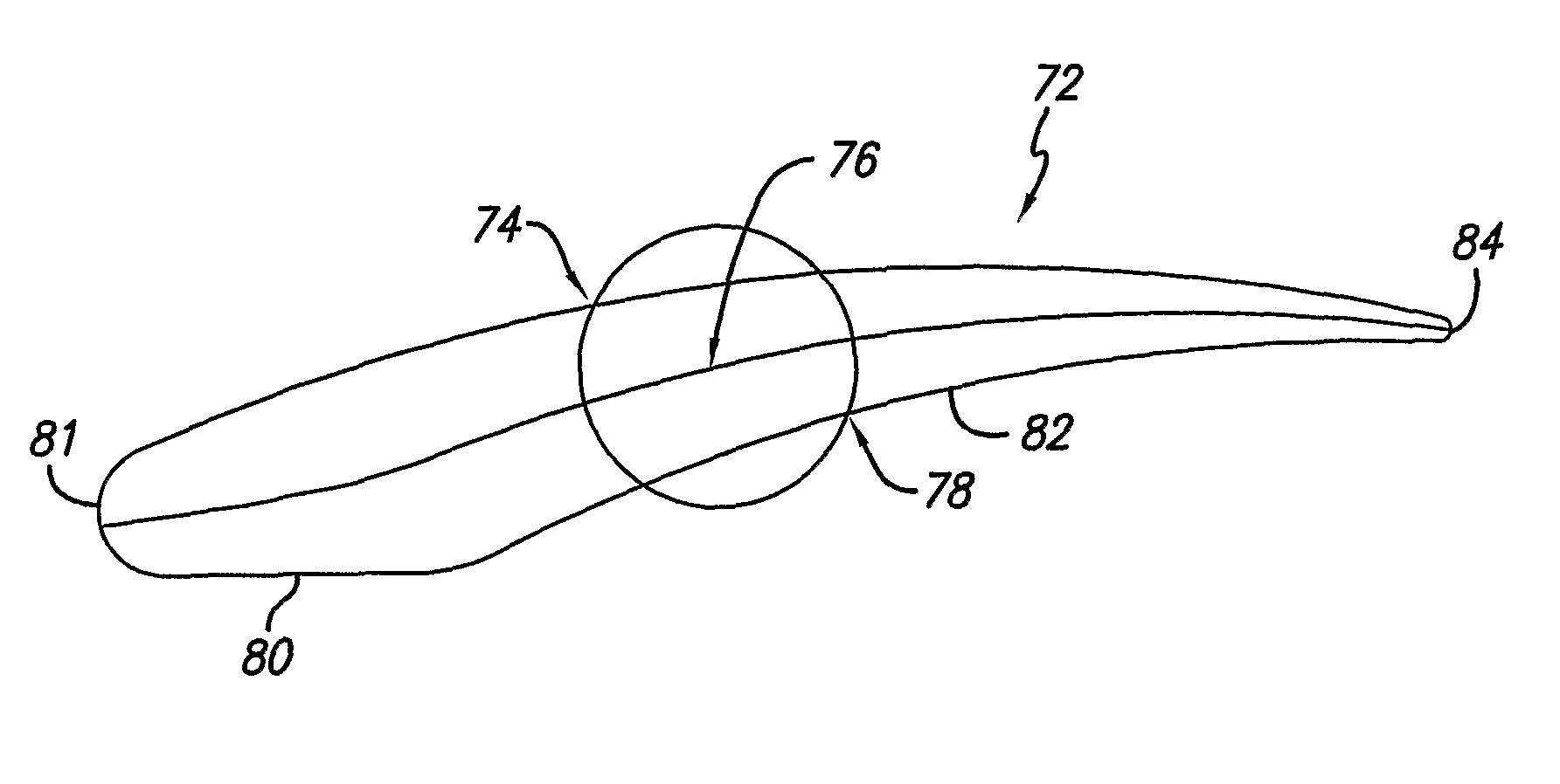
[0019]Generally speaking, the vane is configured having a cambered airfoil profile for purposes of broadening the desired gas flow distribution window within the turbocharger, thereby operating to minimize any unwanted aerodynamic effects within a turbine housing and improve turbocharger operating efficiency when compared to conventional turbocharger vane designs.

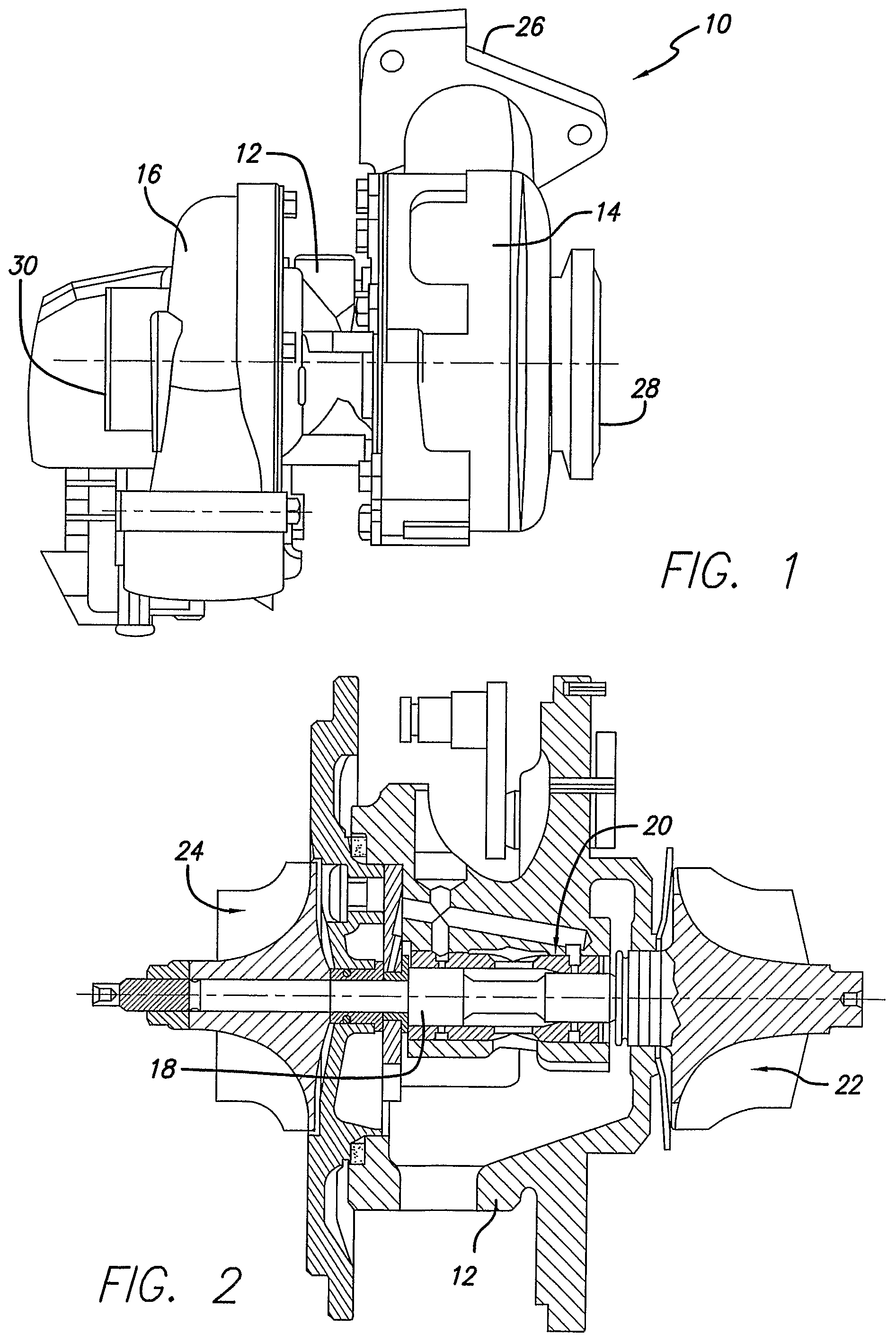
[0020]Referring to FIG. 1, a turbo...


PUM


Abstract

Various cambered vanes are constructed for use within a vaned turbocharger and include an inner airfoil surface oriented adjacent a turbine wheel, and an outer airfoil surface oriented opposite the inner airfoil surface. The inner and outer airfoil surfaces define a vane airfoil thickness. A cambered vane leading edge or nose is positioned along a first inner and outer airfoil surface junction, and a vane trailing edge positioned along a second inner and outer surface junction. The vane inner and outer airfoil surfaces are specially configured to provide a vane camberline having a curved section, which can. provide for improved gas flow distribution, thereby increasing the effective operating range of the turbocharger.

Description

FIELD OF INVENTION[0001]This invention relates generally to the field of turbochargers and, more particularly, to variable geometry turbochargers using movable vanes that are specially shaped for the purpose of widening the operating window and maximizing flow efficiency within the turbocharger.BACKGROUND OF THE INVENTION[0002]Turbochargers for gasoline and diesel internal combustion engines are devices known in the art that are used for pressurizing or boosting the intake air stream, routed to a combustion chamber of the engine, by using the heat and volumetric flow of exhaust gas exiting the engine. Specifically, the exhaust gas exiting the engine is routed into a turbine housing of a turbocharger in a manner that causes an exhaust gas-driven turbine to spin within the housing. The exhaust gas-driven turbine is mounted onto one end of a shaft that is common to a radial air compressor mounted onto an opposite end of the shaft and housed in a compressor housing. Thus, rotary action ...

Claims


Application Information

Patent Timeline
Patent Type & Authority Patents(United States)
IPC IPC(8): F04D29/46F01D5/14F01D17/16
CPCF01D5/141F01D17/165F05D2220/40
Inventor CASTAN, JOEL P.
Owner HONEYWELL INT INC
Why Eureka
Try Eureka