Device for detecting absolute angle of multiple rotation and angle detection method

a technology of multiple rotation and detection method, applied in the direction of instruments, galvano-magnetic hall-effect devices, transportation and packaging, etc., can solve the problems of complicated structure, large space required, complicated structure, etc., and achieve the effect of easy calculation of positive or negative, large latitude, and highly reliable determination of positive or negativ

Inactive Publication Date: 2010-08-10
NTN CORP
View PDF23 Cites 8 Cited by
  • Summary
  • Abstract
  • Description
  • Claims
  • Application Information

AI Technical Summary

Benefits of technology

[0017]According to this construction, the reduction gear mechanism of a high reduction gear ratio can be constructed with a inscribed planetary gear mechanism, which includes the eccentric ring, the internally threaded member and the externally threaded member, and a uniform speed internal gear mechanism which includes the externally threaded member and the speed reducing member. Because of this, by detecting the absolute position of the speed reducing member of the reduction gear mechanism, the wide range of multi-rotation angles can be detected. Also, by using the inscribed planetary gear mechanism and the uniform speed internal gear mechanism for the reduction gear mechanism, the multiple rotation absolute angle detecting device of a through-shaft type can be constructed. In view of these, a high reduction gear ratio can be obtained with the reduction gear mechanism of the through-shaft type and, therefore, the wide range of multi-rotation angles can be detected with a compact structure. Where the rotatable member referred to above is a rotary shaft, for example, a rotatable raceway member of a bearing assembly including a rotary shaft, it can be largely applied to various machines and equipments of a kind including a bearing assembly.
[0053]As hereinabove described, when the boundary value curve LB is set to a line intermediate between the phase during the rotation in the positive direction and the phase during the rotation in the negative direction, a tolerance for any error and / or noises can have a large latitude, allowing a highly reliable determination of the positive or negative. Also, by setting the determining condition, calculation of the determination of the positive or negative can be accomplished easily. It is to be noted that even where the single rotation detecting unit and the multiple rotation detecting unit output a sinusoidal wave, it is preferred that signals a and b of sinusoidal waveforms displaced 90° relative to each other, which exhibit one cycle for each complete rotation (wherein “a” represents a sinusoidal wave and “b” represents a cosine wave), are detected from the two Hall ICs arranged in 90° phase difference relation to each other, and, after the sawtooth wave is prepared by calculating the absolute angle of each complete rotation by means of a quadrant determination of each output of a / b while the half value Vc / 2 of the power source voltage Vc is set to zero, the boundary value curve is set to lie intermediate between the phase during the rotation in the positive direction and the phase during the rotation in the negative direction as described above, and the determination of the positive or negative is carried out by setting the determining conditions as described above.

Problems solved by technology

However, the device, in which the reduction gear mechanism including a combination of the worm and the worm wheel such as disclosed in the Japanese Laid-open Patent Publication No. 2001-289671 referred to above, has a problem in what although a relatively large reduction gear ratio can be enjoyed, not only is the structure complicated because of the shafts lying perpendicular to each other, but a relatively large space is required.
Moreover, since it makes use of a plurality of shafts, a relatively large space is required for installation of the bearing assembly, resulting in complicating of the structure.
According to the structure, which utilizes the planetary gear mechanism such as disclosed in the Japanese Laid-open Patent Publication No. 2002-340545 referred to above, a problem has been found as to how the gears (particularly, planetary gears) are to be supported as well as the increased number of the gears employed.
Additionally, an attempt to increase the reduction gear ratio tends to result in increase of the dimensions in a direction radially of the mechanism.
Also, the device disclosed in the Japanese Laid-open Patent Publication No. 2004-308724 referred to above, in which the to-be-detected member is fitted to the retainer, is incapable of accurately detecting the absolute angle since during the rotation or the halt and start of rotation, rolling members often tend to undergo slippage.

Method used


Image

  • Device for detecting absolute angle of multiple rotation and angle detection method
  • Device for detecting absolute angle of multiple rotation and angle detection method
  • Device for detecting absolute angle of multiple rotation and angle detection method

Examples


first embodiment

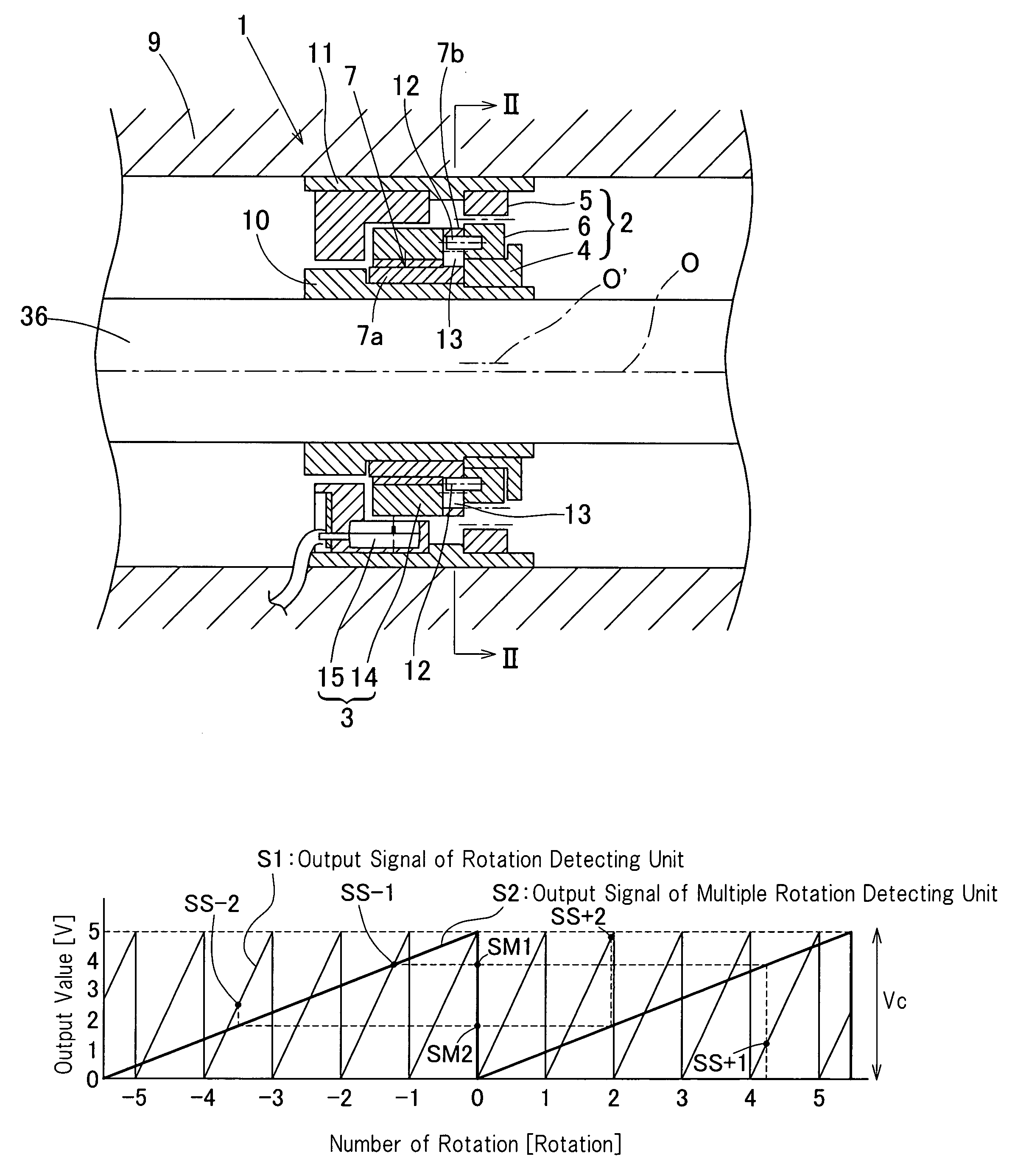
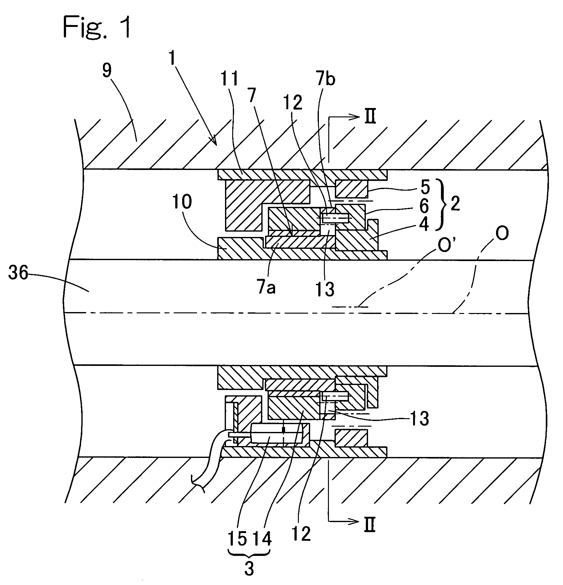
[0109]One end of the inner periphery of the inner race 22 is fixedly mounted with a cylindrical rotor housing 10 by means of press-fitting, and the outer periphery of the rotor housing 10 is fixedly mounted with the eccentric ring 4 by means of press-fitting bond in a manner similar to that in the previously described

[0110]The stator housing 11 is fixedly press-fitted adjacent one end of the outer periphery of the outer race 23, which is on the same side as the protruding end of the rotor housing 10, in a manner similar to that in the previously described first embodiment, and the internally threaded member 5 referred to above is fixedly press-fitted in or bonded to the inner periphery of the stator housing 11.

[0111]In FIG. 8, the to-be-detected member 14 is shown as employed in the form of a magnetic encoder and the detecting member 15 is shown as employed in the form of a sensor housing, in which Hall ICs are arranged having been displaced 90° in phase from each other. In such cas...

sixth embodiment

[0116]In the sixth embodiment described above, the multiple rotation absolute angle detecting mechanism comprised of the multiple rotation absolute angle detecting device 1 and the single rotation detecting mechanism 8 is disposed between two rolling bearing units 21A and 21B that are juxtaposed relative to each other in a direction axially thereof. In such case, the rotor housing 10 is fixed straddling respective inner peripheries of inner races 22A and 22B of the two rolling bearing units 21A and 21B and the stator housing 11 is fixed straddling respective outer peripheries of outer races 23A and 23B thereof.

[0117]Also, in the sixth embodiment, a spacer 25 is interposed between the outer race 23A and the internally threaded member 5; a spacer 26 is interposed between the internally threaded member 5 and the detecting member 15 of the multiple rotation detecting unit 3; and a spacer 27 is interposed between the to-be-detected member 19 of the single rotation detecting unit 18 and t...

eighth embodiment

[0122]FIG. 13 illustrates a ninth preferred embodiment of the present invention. This multiple rotation absolute angle detecting device incorporated bearing assembly generally identified by C is similar to that shown in and described with reference to FIG. 12, but differs therefrom in that the two rolling bearing units 21A and 21B are replaced with one rolling bearing unit 21 and the rotor housing 10A and the other rotor housing 10B are fixedly press-fitted to one end of the outer periphery of the inner race 22 and the opposite end of the outer periphery of the inner race 22, respectively. Also, the stator housings 11A and 11B are fixedly press-fitted to one end of the inner periphery of the outer race 23 and the other end of the inner periphery of the outer race 23, respectively. The eccentric ring 4 and the speed reducing member 7 are provided in the outer periphery of the rotor housing 10A, and the internally threaded member 5 and the detecting member 15 of the multiple rotation...


PUM


Abstract

A multiple rotation absolute angle detecting device includes a reduction gear mechanism having an eccentric ring fitted to a rotatable member, an internally threaded member in a stationary member, an externally threaded member engageable with the internally threaded member, and a speed reducing member to which rotation is transmitted from the externally threaded member. The externally threaded member undergoes a speed-reduced rotation at a reduction gear ratio of 1 / L (L represents an arbitrarily value exceeding 1) about an axis O′ of rotation of the eccentric ring and the speed reducing member rotates around the rotatable member at a speed equal to that of the externally threaded member. A multiple rotation detecting unit for outputting a sinusoidal or sawtooth wave having one period per rotation includes a to-be-detected member in the speed reducing member and a detecting member in the stationary member that confronts the to-be-detected member.

Description

BACKGROUND OF THE INVENTION[0001]1. Field of the Invention[0002]The present invention relates to a device for detecting the absolute angle of multiple rotations such as, for example, the absolute steering angle of steering, to a bearing assembly equipped with such an absolute angle detecting device and to a method of detecting the angle thereof.[0003]2. Description of the Prior Art[0004]The above-mentioned type of multiple rotation absolute angle detecting device has been suggested in the art, in which using a reduction gear mechanism made up of a combination of a worm and a worm wheel or a reduction gear mechanism utilizing a set of spur gears, output signals outputted respectively from an encoder for detecting an absolute angle within one complete rotation and an encoder for detecting multiple rotation are synthesized by a signal processing circuit to thereby detect the absolute angle of multiple rotations. (See, for example, the Japanese Laid-open Patent Publications No. 2001-289...

Claims


Application Information

Patent Timeline
Patent Type & Authority Patents(United States)
IPC IPC(8): G01B7/30H01L43/06G01M17/06
CPCB62D15/0215B62D15/0245F16C41/007G01B7/30G01D5/04G01D5/2451G01D2205/28G01D2205/26
Inventor ISOBE, HIROSHIOZAKI, TAKAYOSHISASAKI, NORIHIKO
Owner NTN CORP
Why Eureka
Try Eureka