Low-average-power parabolic pulse amplification

a parabolic pulse and low-average-power technology, applied in the field of optical amplifiers, can solve problems such as unbalanced gain and improper conditions for parabolic pulse amplification

Active Publication Date: 2010-08-10
INSTITUT NATIONAL D'OPTIQUE
View PDF17 Cites 19 Cited by
  • Summary
  • Abstract
  • Description
  • Claims
  • Application Information

AI Technical Summary

Problems solved by technology

This results in an unbalanced gain and to improper conditions for parabolic pulse amplification.

Method used


Image

  • Low-average-power parabolic pulse amplification
  • Low-average-power parabolic pulse amplification
  • Low-average-power parabolic pulse amplification

Examples


Embodiment Construction

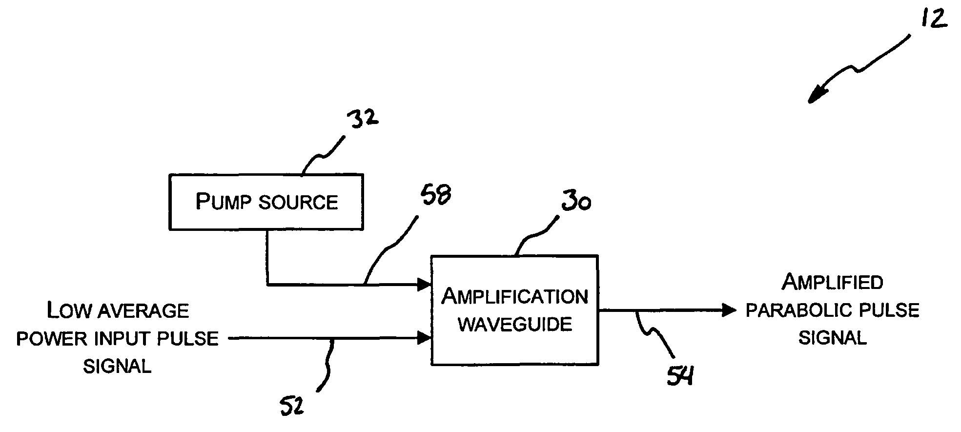
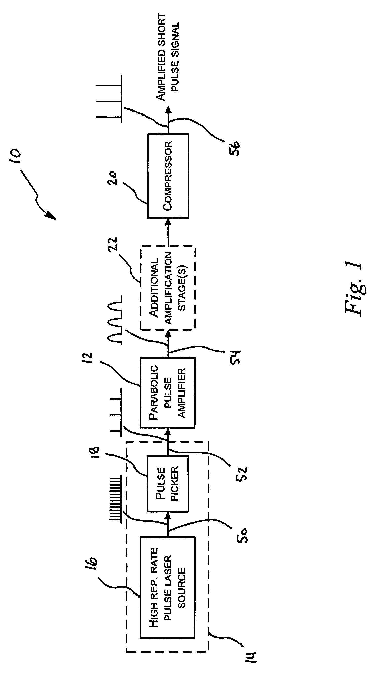
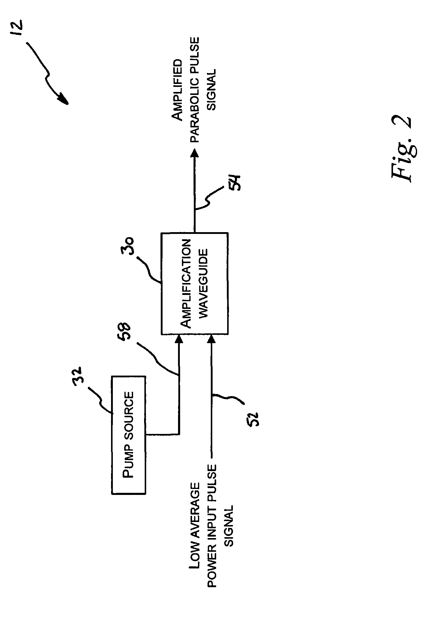
[0022]Referring now to the drawings, FIG. 1 shows a low-repetition-frequency short-pulse light source system 10 incorporating a parabolic pulse amplifier 12. The system 10 is used to produce a low-Pulse-Repetition-Frequency (PRF) femtosecond pulse light signal having a wavelength of 1064 nm, from a high-PRF pulse laser source 16. The system 10 comprises a low-PRF pulse light source 14 which is amplified using a parabolic pulse amplifier 12. In this example, the low-PRF pulse light source 14 is provided by cascading a high-PRF pulse light source 16 and a pulse picker 18 for selecting a fraction of the pulses produced by the high-PRF pulse light source 16 in order to reduce the PRF.

[0023]In this case, the high-PRF pulse laser source 16 is a commercially available mode-locked fibre laser manufactured by Calmar Optcom™. Femtosecond fibre laser oscillators usually produce a high-PRF pulse signal 50 having a PRF of the order of 5 to 100 MHz. For many applications, a PRF below 5 MHz, and t...


PUM


Abstract

There is provided a parabolic pulse amplifier for amplifying a pulse light signal. The amplifier comprises an ytterbium-doped amplification waveguide pumped using a pump source with a pump central wavelength substantially offset from the absorption transition peak wavelength. The pump wavelength is selected such that the absorption coefficient of pump light and the gain coefficient of the signal are substantially equal in the amplification waveguide such that the amplification gain is distributed substantially uniformly along the amplification waveguide.

Description

TECHNICAL FIELD[0001]The present invention relates to optical amplifiers. More particularly, the present invention relates to parabolic pulse amplification.BACKGROUND ART[0002]Optical fibre amplifiers are used to amplify either continuous or pulsed optical signals. There are two main techniques for amplifying ultrashort light pulses, such as femtosecond pulses, using optical fibre amplifiers.[0003]The first technique, called fibre chirped-pulse amplification, uses a combination of three subcomponents, namely a stretcher, an optical fibre amplifier and a compressor. The stretcher is a dispersive optical element which introduces a spectral chirp in the short pulses to be amplified so that the frequency content of each pulse is spread over time. As a result, the pulse duration is increased, and the peak power of the pulse is reduced.[0004]The chirped pulses are then injected in a standard optical fibre amplifier. Pulse amplification takes place with low nonlinear effects, as the peak p...

Claims


Application Information

Patent Timeline
Patent Type & Authority Patents(United States)
IPC IPC(8): H04B10/17
CPCH01S3/06754H01S3/2316H01S3/0057H01S3/06758H01S3/094015H01S3/094023H01S3/1608
Inventor BRUNET, FRANCOISDESBIENS, LOUIS
Owner INSTITUT NATIONAL D'OPTIQUE
Why Eureka
Try Eureka