Bidirectional hydraulic transformer

a hydraulic transformer and bi-directional technology, applied in the direction of fluid couplings, clutches, servomotors, etc., can solve the problems of energy waste, additional energy must be utilized to remove heat from the system, energy that could have been utilized to move the actuator is lost from the fluid, etc., to increase the pressure of the second flow, increase the fluid pressure, and increase the fluid pressure

Inactive Publication Date: 2010-08-17
CATERPILLAR INC
View PDF24 Cites 31 Cited by
  • Summary
  • Abstract
  • Description
  • Claims
  • Application Information

AI Technical Summary

Benefits of technology

[0011]In one aspect, the present disclosure is directed to a hydraulic transformer. The hydraulic transformer may include a housing, and a first pumping mechanism disposed within the housing and rotated in a first direction by fluid pressure. The hydraulic transformer may also include a second pumping mechanism disposed within the housing and rotated by the first pumping mechanism in the first direction to increase the fluid pressure. The hydraulic transformer may further include a common shaft connecting the first and second reversible pumping mechanisms. One of the first and second pumping mechanisms may also be rotated in a second direction opposite the first by fluid pressure. The other of the first and second pumping mechanisms may also be rotated by the one of the first and second pumping mechanisms in the second direction to increase the fluid pressure.
[0012]In another aspect, the present disclosure is directed to hydraulic circuit. The hydraulic circuit may include an actuator having a first pr

Problems solved by technology

One problem associated with this type of hydraulic arrangement is the energy wasted when pressurized fluid flow is throttled through a valve in order to control movement speed of the actuator.
In this situation, energy that could have been utilized to move the actuator is lost from the fluid, and additional energy must be utilized to remove the heat from the system.
Another problem associated with this type of hydraulic arrangement involves the magnitude of the pressure required to move the actuators, particularly when the actuators are heavily loaded.
This requirement increases the size of the pump and, subsequently, the overall cost of the machine.
In addition, when the pressures are significantly high, precise movement control of the actuators can be difficult, and not all actuators powered by a common pump require the same high pressure.
As described above, throttling of the pressurized fluid is an inefficient way to achieve the desired

Method used


Image

  • Bidirectional hydraulic transformer
  • Bidirectional hydraulic transformer
  • Bidirectional hydraulic transformer

Examples


Embodiment Construction

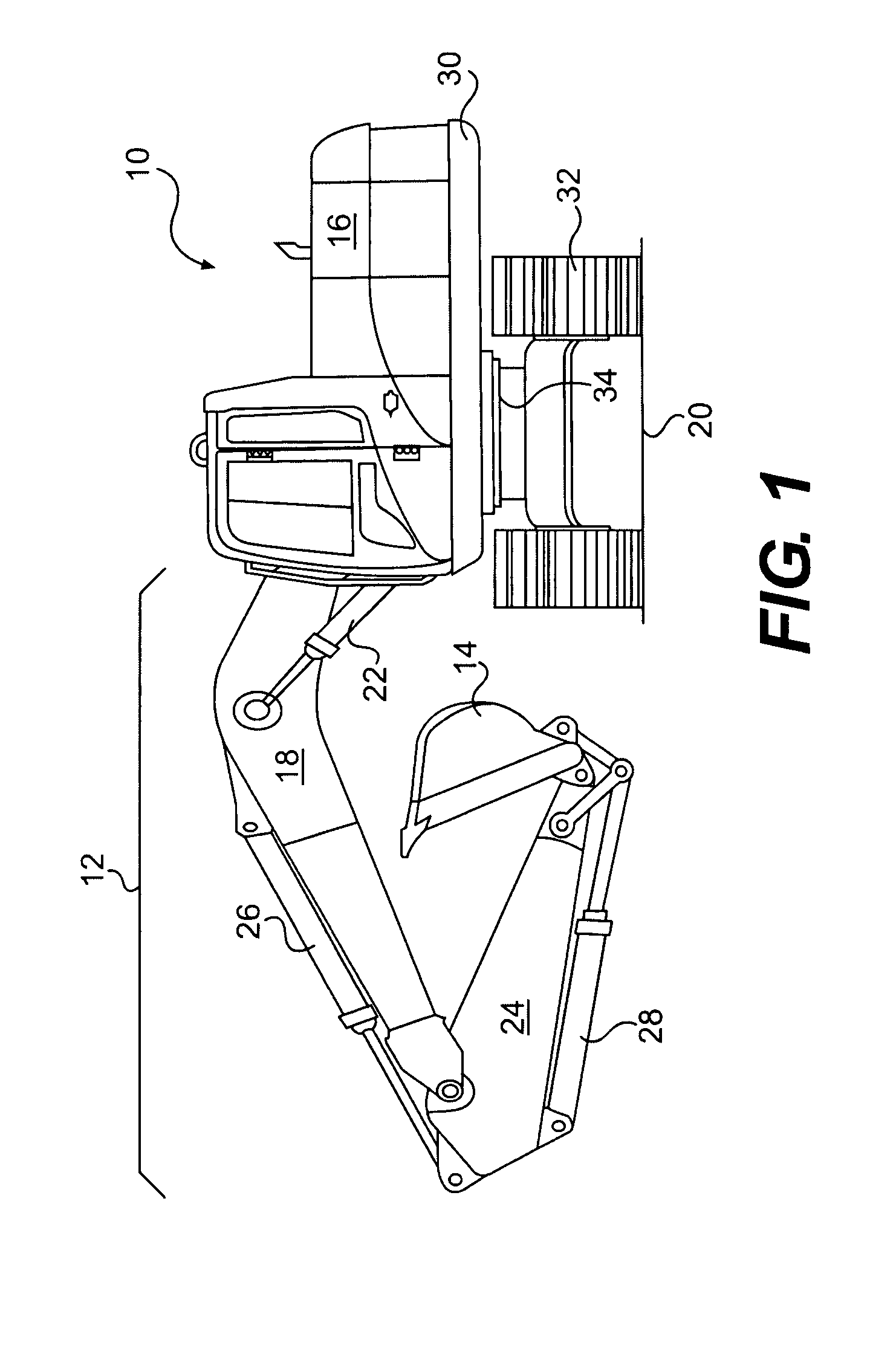
[0017]FIG. 1 illustrates an exemplary machine 10 having multiple systems and components that cooperate to accomplish a task. Machine 10 may embody a fixed or mobile machine that performs some type of operation associated with an industry such as mining, construction, farming, transportation, or any other industry known in the art. For example, machine 10 may be an earth moving machine such as the excavator depicted in FIG. 1. Alternatively, machine 10 may be a dozer, a loader, a backhoe, a motor grader, a haul truck, or any other earth-moving or task-performing machine. Machine 10 may include an implement system 12 configured to move a work tool 14, and a power source 16 that drives implement system 12.

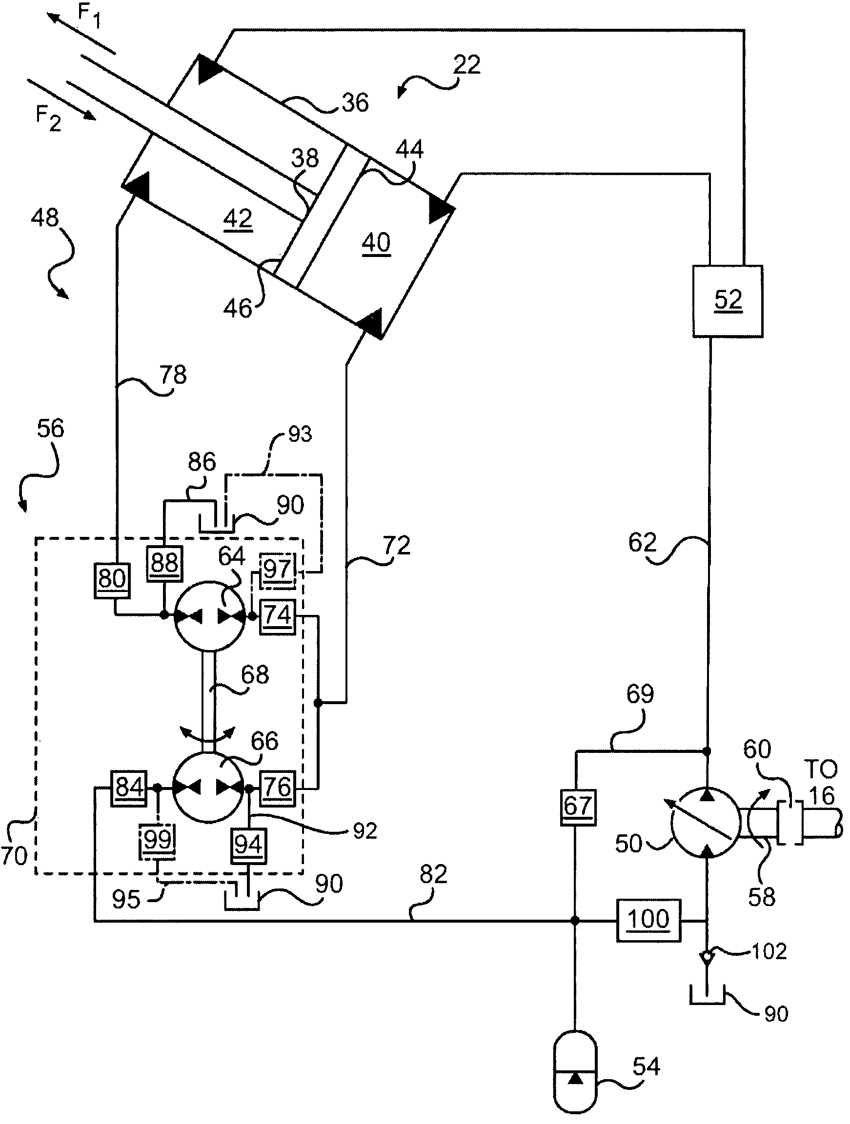
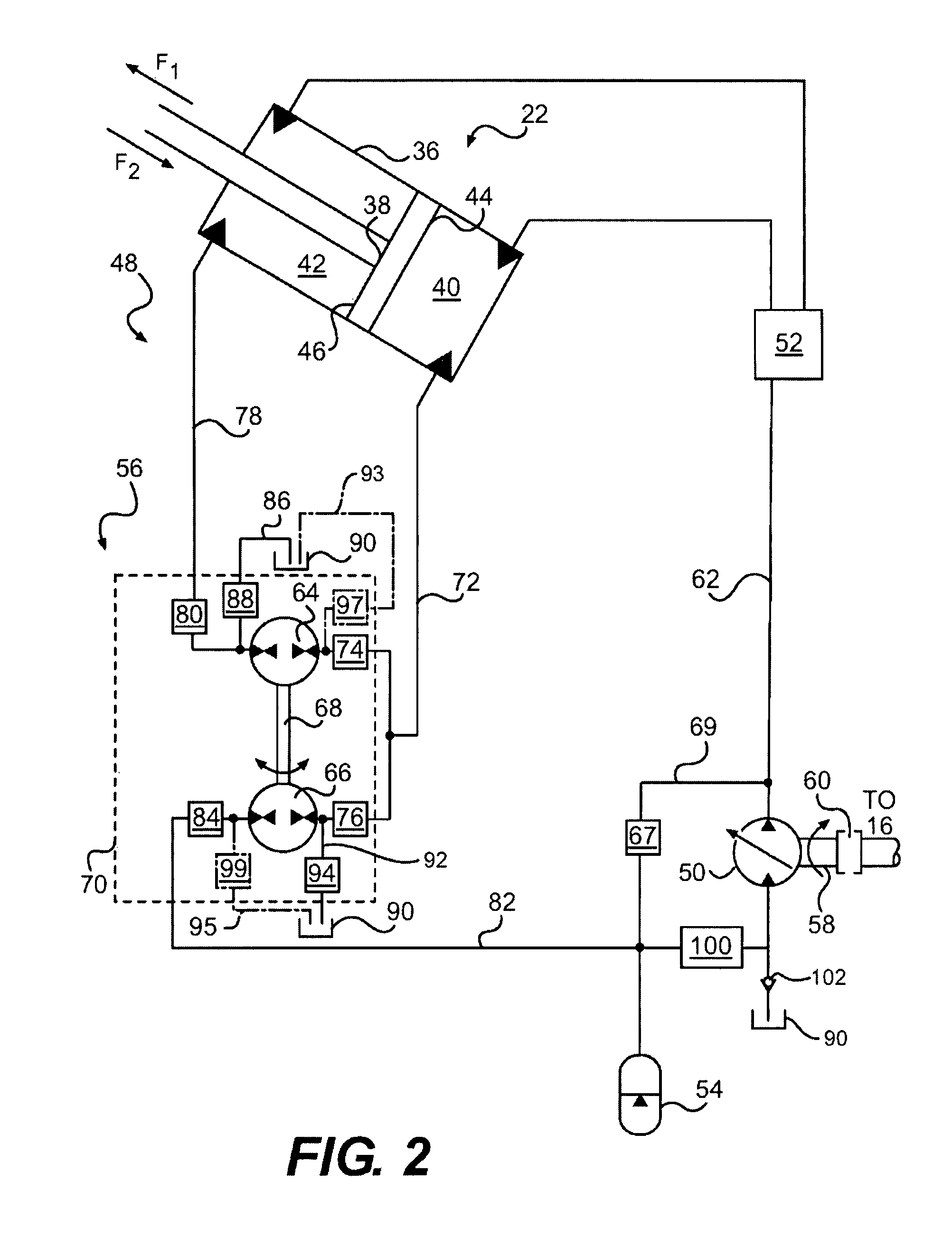
[0018]Implement system 12 may include a linkage structure moved by fluid actuators to position and operate work tool 14. Specifically, implement system 12 may include a boom member 18 that is vertically pivotal about an axis relative to a work surface 20 by a pair of adjacent, double-...


PUM


Abstract

A hydraulic transformer is disclosed. The hydraulic transformer may have a housing, and a first pumping mechanism disposed within the housing and rotated in a first direction by fluid pressure. The hydraulic transformer may also have a second pumping mechanism disposed within the housing and rotated by the first pumping mechanism in the first direction to increase the fluid pressure. The hydraulic transformer may further have a common shaft connecting the first and second reversible pumping mechanisms. One of the first and second pumping mechanisms may also be rotated in a second direction opposite the first by fluid pressure. The other of the first and second pumping mechanisms may also be rotated by the one of the first and second pumping mechanisms in the second direction to increase the fluid pressure.

Description

[0001]This application is based on and claims the benefit of priority from U.S. Provisional Application No. 60 / 857,491, filed Nov. 8, 2006.TECHNICAL FIELD[0002]The present disclosure relates generally to a hydraulic transformer, and more particularly, to a bidirectional hydraulic transformer usable for energy recuperation.BACKGROUND[0003]Hydraulic actuators such as cylinders having an extendable and retractable rod and piston are utilized to accomplish a variety of tasks. These actuators are connected to a pump that provides pressurized fluid to chambers within the actuators. As the pressurized fluid moves into or through the chambers, the pressure of the fluid acts on hydraulic surfaces of the chambers to effect movement of the rod and piston. When the pressurized fluid is drained from the chambers it is returned to a low pressure tank. The speed at which the fluid flows into and out of the chambers affects the extension and retraction speeds of the actuator, while the pressure in ...

Claims


Application Information

Patent Timeline
IPC IPC(8): F16D31/02
CPCF15B11/024F15B21/14F15B2211/20538F15B2211/20546F15B2211/20569F15B2211/20576F15B2211/212F15B2211/214F15B2211/30525F15B2211/3144F15B2211/31576F15B2211/327F15B2211/88
Inventor KHALIL, RABIE E.
Owner CATERPILLAR INC
Why Eureka
Try Eureka