Method of sector probe driving and ultrasound diagnostic apparatus

a technology of ultrasound diagnostic apparatus and sector probe, which is applied in the direction of instruments, ultrasonic/sonic/infrasonic image/data processing, mechanical vibration separation, etc., can solve the problems of inability and inability of the former ultrasound diagnostic apparatus to operate, and the conventional ultrasound diagnostic apparatus has a problem of incapacity

Inactive Publication Date: 2010-08-17
GE MEDICAL SYST GLOBAL TECH CO LLC
View PDF19 Cites 81 Cited by
  • Summary
  • Abstract
  • Description
  • Claims
  • Application Information

AI Technical Summary

Benefits of technology

[0013]The sector probe driving method of the third object of invention selects and drives vibration elements of N in number, which is equal to the number of channels of the transmitter or receiver, at random out of the L vibration elements of the sector probe. The resulting ability of sector scanning enables the sector probe driving by use of the transmitter / receiver for the convex probe and linear probe. An irregular distribution of vibration elements alleviates the emergence of grating lobe.
[0042]According to the inventive sector probe driving method and ultrasound diagnostic apparatus, it is possible to implement the sector scanning properly by driving the sector probe by use of the transmitter / receiver for the convex probe and linear probe.

Problems solved by technology

Due to this difference, the conventional ultrasound diagnostic apparatus has a problem of incapacity for driving a sector probe by using the transmitter / receiver for a convex probe and linear probe.
It has not been possible for the former ultrasound diagnostic apparatus to use the sector probe of the latter apparatus.

Method used


Image

  • Method of sector probe driving and ultrasound diagnostic apparatus
  • Method of sector probe driving and ultrasound diagnostic apparatus
  • Method of sector probe driving and ultrasound diagnostic apparatus

Examples


first embodiment

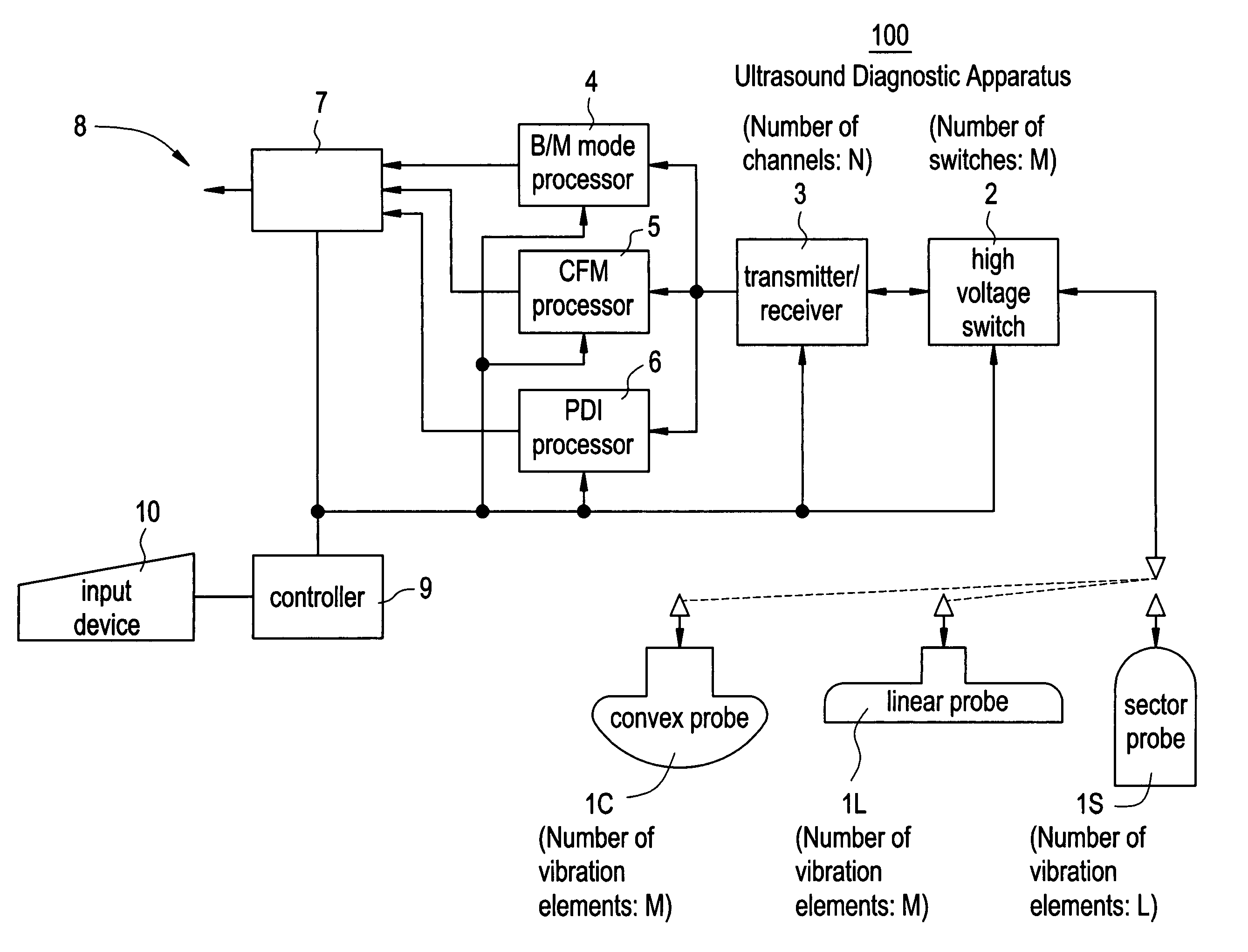
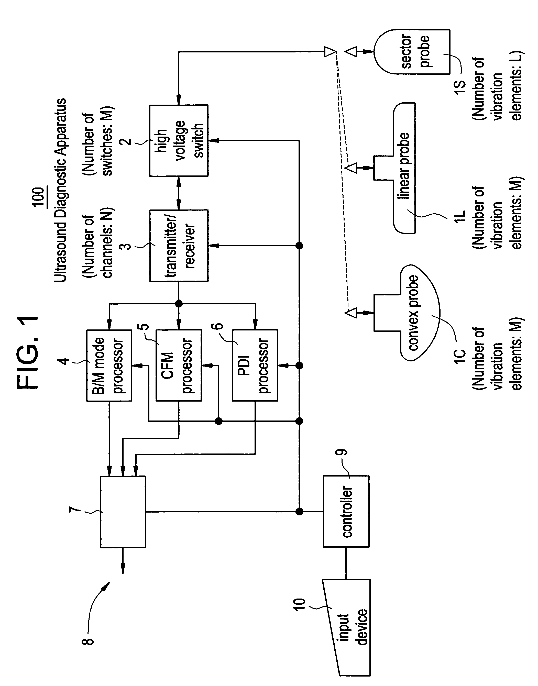
[0064]FIG. 1 is a block diagram showing an ultrasound diagnostic apparatus 100 based on a first embodiment.

[0065]The ultrasound diagnostic apparatus 100 includes a convex probe 1C having vibration elements of M in number, a linear probe 1L having vibration elements of M in number, a sector probe 1S having vibration elements of L in number, a high voltage switch 2 including switches of M in number, a transmitter / receiver 3 of N channels, a B / M mode processor 4, a CFM (Color Flow Mapping) processor 5, a PDI (Power Doppler Image) processor 6, a DSC (Digital Scan Converter) 7, a display device 8, a controller 9, and an input device 10.

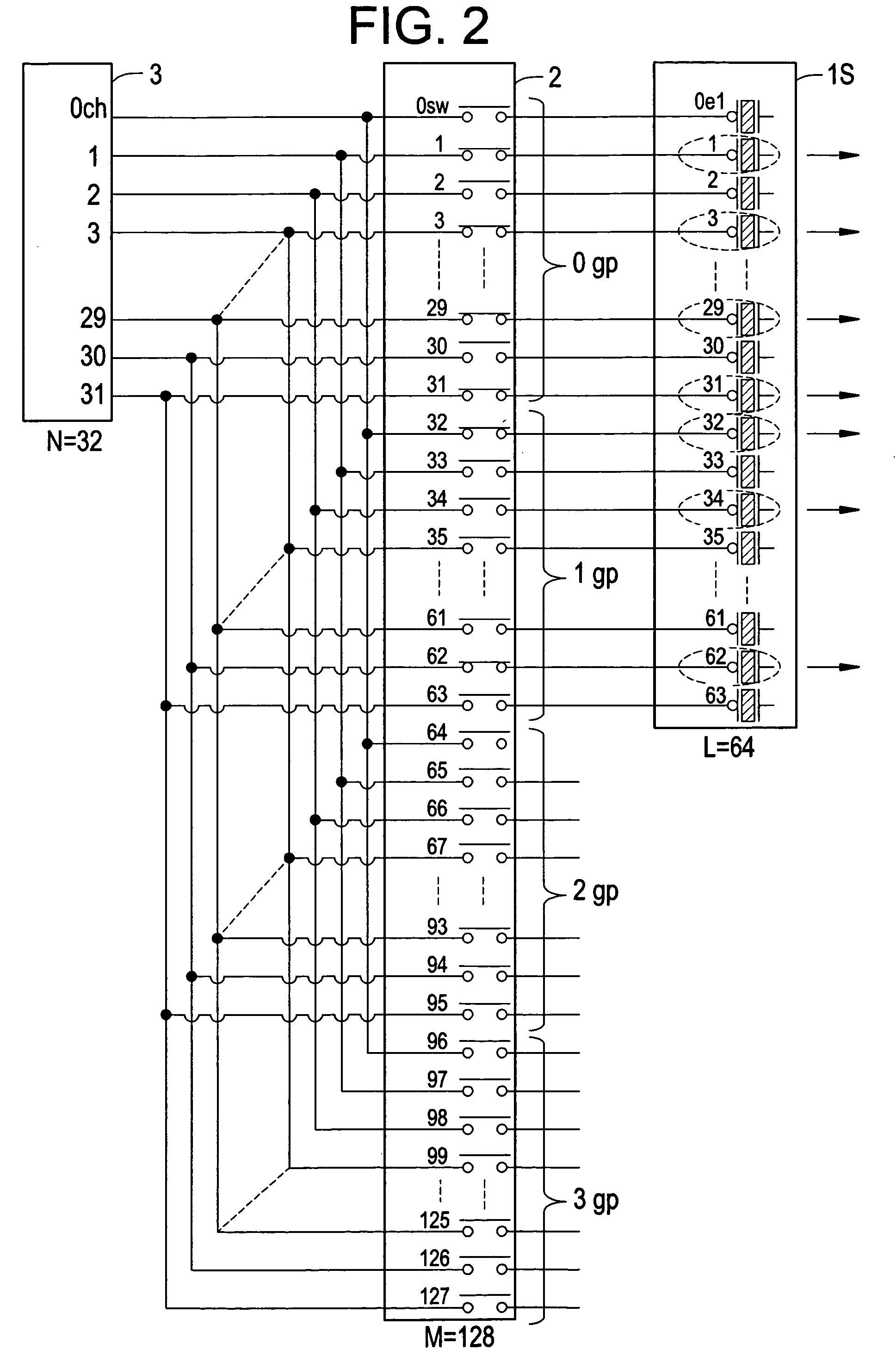
[0066]FIG. 2 is an explanatory diagram showing the connection among the sector probe 1S, high voltage switch 2, and transmitter / receiver 3 of the first embodiment. The parameters are set to be N=32, M=128 and L=64 in this embodiment.

[0067]Each n-th channel, where n takes 0 through 31, is connected in parallel fashion to the n-th switch, the (n+32)th switch...

second embodiment

[0081]FIG. 7 is an explanatory diagram showing the connection among the sector probe 1S, high voltage switch 2, and transmitter / receiver 3 of a second embodiment. The parameters are set to be N=32, M=128 and L=64 in this embodiment.

[0082]Each n-th channel, where n takes 0 through 31, is connected in parallel fashion to the n-th switch, the (n+32)th switch, . . . , and the (n+96)th switch.

[0083]The sector probe 1S has its 0th through 63rd vibration elements connected to the 0th through 63rd switches, respectively.

[0084]The controller 9 turns on the 16th through 47th switches and turns off other switches which are connected with vibration elements. Consequently, only the 16th through 47th vibration elements located in the central section of the alignment of vibration elements are driven.

[0085]FIG. 8 is an explanatory diagram showing the correspondence between the channels of the transmitter / receiver 3 and the vibration elements of the sector probe 1S of the second embodiment. Vibratio...

third embodiment

[0088]FIG. 9 is an explanatory diagram showing the connection among the sector probe 1S, high voltage switch 2, and transmitter / receiver 3 of a third embodiment. The parameters are set to be N=32, M=128 and L=128 in this embodiment.

[0089]Each n-th channel, where n takes 0 through 31, is connected in parallel fashion to the n-th switch, the (n+32)th switch, . . . , and the (n+96)th switch.

[0090]The sector probe 1S has its 0th through 127th vibration elements connected to the 0th through 127th switches, respectively.

[0091]Each set of a m-th through (m+31)th switches, where m takes 0, 32, 64 and 96), are united to be a (m / 32)th switch group.

[0092]The controller 9 selects 32 vibration elements which are located at a constant pitch or virtually constant pitch and are not connected to same channels, turns on the 32 switches only, and turns off other switches which are connected with vibration elements. Consequently, only 32 vibration elements which are distributed at a constant pitch or v...


PUM


Abstract

The transmitter / receiver for a convex probe and linear probe are used to drive a sector probe. Usually, when an ultrasound diagnostic apparatus using a convex probe and linear probe uses a sector probe, it selects vibration elements of N in number, which is equal to the number of channels of the sector probe, out of vibration elements of L in number (N is smaller than L), so that the selected elements are distributed at a virtually constant pitch in the alignment of vibration elements, and turns on only high voltage switches which are connected with the selected vibration elements to implement the sector scanning with the transmitter / receiver. It becomes possible to implement the sector scanning by using the transmitter / receiver having channels less than the number of vibration elements of the sector probe.

Description

CROSS REFERENCE TO RELATED APPLICATIONS[0001]This application claims the benefit of Japanese Application No. 2003-163069 filed Jun. 9, 2003.BACKGROUND OF THE INVENTION[0002]The present invention relates to a method of sector probe driving and an ultrasound diagnostic apparatus, and particularly to a method of sector probe driving and an ultrasound diagnostic apparatus which are capable of driving a sector probe by using the transmitter / receiver for a convex probe and linear probe.[0003]An ultrasound diagnostic apparatus using a convex probe and linear probe is equipped with a transmitter / receiver having a 0th through 31st channels and a high voltage switch including a 0th through 127th switches, for example, with each n-th channel, where n takes 0 through 31, being connected in parallel fashion to the n-th switch, the (n+32)th switch, . . . , and the (n+96)th switch. The 0th through 127th switches are connected to the 0th through 127th vibration elements, respectively, of the convex...

Claims


Application Information

Patent Timeline
Patent Type & Authority Patents(United States)
IPC IPC(8): G01R33/20A61B8/06A61B8/00A61B8/08B06B1/02G01S7/52G10K11/34
CPCG01S7/52049G10K11/341A61B8/06A61B8/08A61B8/13A61B8/4411A61B8/488B06B2201/76A61B8/00
Inventor AMEMIYA, SHINICHI
Owner GE MEDICAL SYST GLOBAL TECH CO LLC
Why Eureka
Try Eureka