System for use in spinal stabilization

a spinal stabilization and system technology, applied in the field of instruments, can solve the problems of reducing nerve function, affecting the recovery of patients, and affecting the recovery of patients, and surgeons have encountered considerable difficulty

Active Publication Date: 2010-08-17
STRYKER EURO OPERATIONS HLDG LLC
View PDF60 Cites 103 Cited by
  • Summary
  • Abstract
  • Description
  • Claims
  • Application Information

AI Technical Summary

Benefits of technology

[0019]According to yet another aspect of the invention, an apparatus for securing a spinal rod to a pedicle screw is provided. The apparatus includes a generally longitudinally body defining a channel, a generally longitudinal pusher member defining a channel, a cannula formed by the channels, a ratchet, a grip extending from the body, a trigger slidingly coupling the pusher member to the body, a handle extending from the tr

Problems solved by technology

Patients that suffer from such conditions usually experience extreme and debilitating pain, as well as diminished nerve function.
Surgeons have encountered considerable difficulty when attempting to use these instruments to insert a spine rod into the seat of the coupling element and then inserting a fastener to secure the se

Method used


Image

  • System for use in spinal stabilization
  • System for use in spinal stabilization
  • System for use in spinal stabilization

Examples


Embodiment Construction

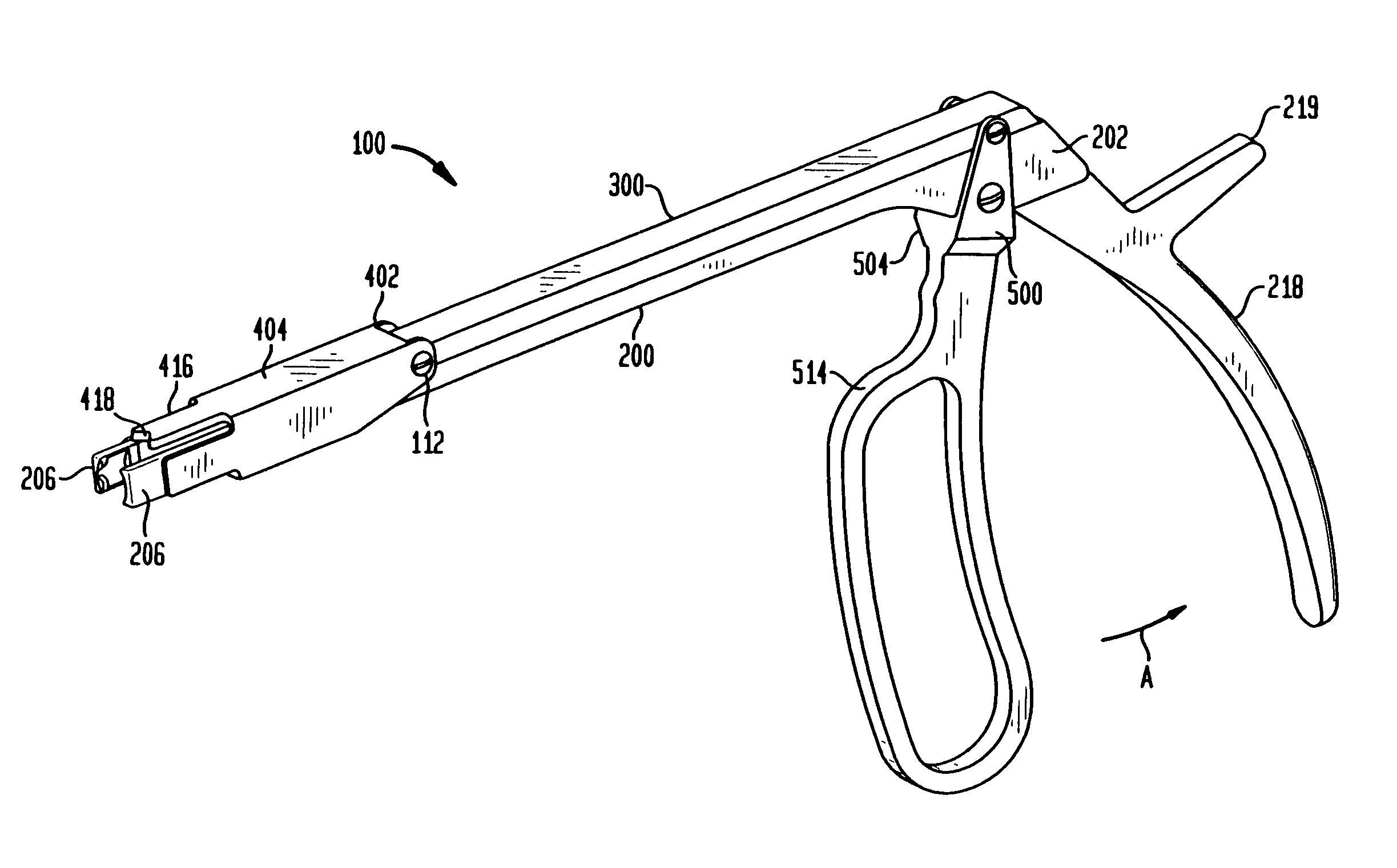
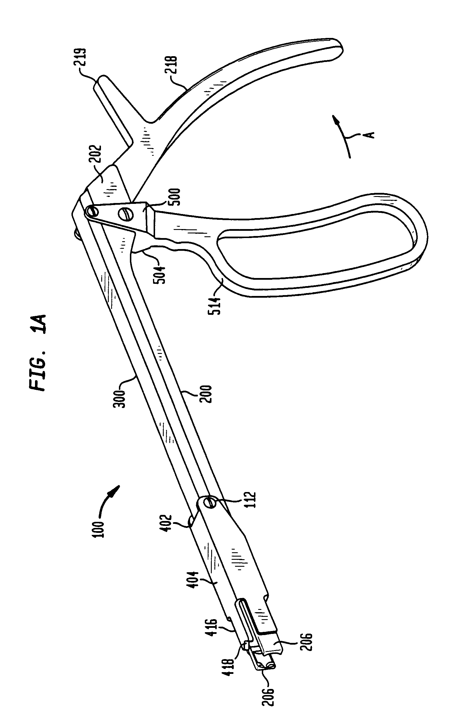
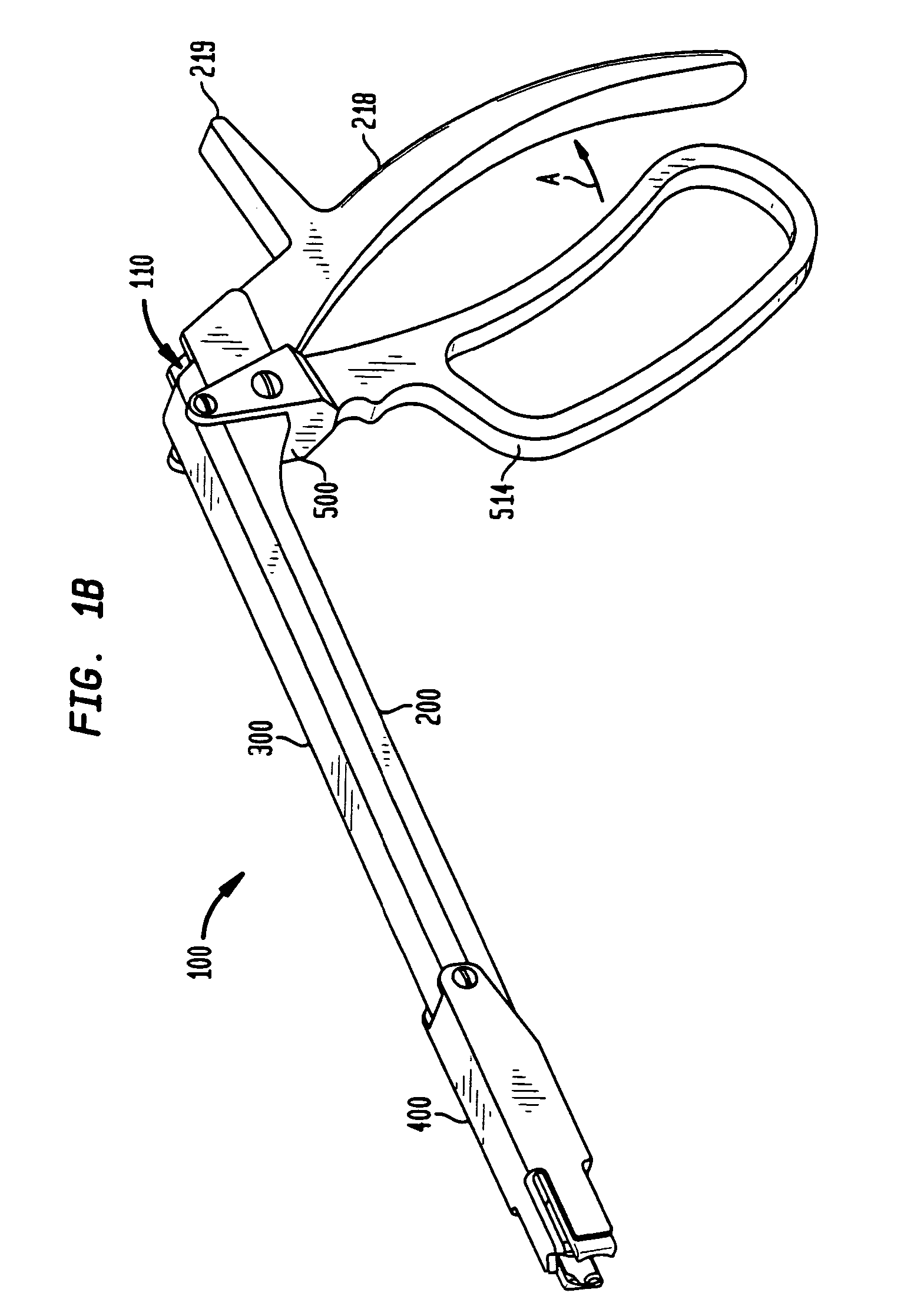
[0042]FIGS. 1A though 1D show an instrument 100 for persuading a rod into 114 a seator recess 102 of an orthopedic device or a coupling element 104. The instrument 100 comprises a generally longitudinal body 200, a slide 300, a sleeve 400 and a trigger 500, each illustrated separately in FIGS. 2, 3, 4, and 5 respectively. The slide 300 and sleeve 400 together form a pusher member.

[0043]Referring now to FIGS. 1A-1E and 2, the body 200 defines a first end 202 and a second end 204. A pair of fingers 206 extend from the second end 204 of the body 200. The fingers 206 each have an interior wall 208 which define indentations 210 and notches 211 that correspond to the shape of the coupling element 104. As shown in FIG. 1E, the coupling element 104 defines grooves 105 for receiving notches 211. The fingers are rigid, but also elastic so that they act in a springing motion so that the application of a force will separate the fingers. Thus, a force may be applied to the body in order to inser...


PUM


Abstract

An apparatus for persuading an orthopedic rod into position in an orthopedic device such as an implant or coupling element is disclosed. The apparatus includes a body, a pusher member and a trigger slidingly coupling the pusher member to the body. The pusher member includes a slide and sleeve attached to the slide. The sleeve includes at least one pusher bar. A ratchet controls the translation of the pusher member along the body to urge the rod into position in the orthopedic device. The pusher member and body define a cannula so that a fastener may be inserted once the rod is in position. The apparatus is operable via a single hand. In addition, a method of urging an orthopedic rod into a recess of an orthopedic device using the rod persuader is provided.

Description

CROSS REFERENCE TO RELATED APPLICATIONS[0001]The present application is a continuation of U.S. application Ser. No. 10 / 124,170 file on Apr. 17, 2002.BACKGROUND OF THE INVENTION[0002]The present invention relates to an instrument for urging an orthopedic rod into a recess in an orthopedic device and more particularly, to an instrument for securing a spinal rod to a coupling element.[0003]The spinal column is a highly complex system of bones and connective tissues that provides support for the body and protects the delicate spinal cord and nerves. The spinal column includes a series of vertebral bodies stacked one atop the other, each vertebral body including an inner or central portion of relatively weak cancellous bone and an outer portion of relatively strong cortical bone. Situated between each vertebral body is an intervertebral disc that cushions and dampens compressive forces exerted upon the spinal column. A vertebral canal containing the spinal cord and nerves is located behi...

Claims


Application Information

Patent Timeline
IPC IPC(8): A61B17/56A61B17/70A61B17/88
CPCA61B17/7086A61B17/7032
Inventor MARKWORTH, AARONCROZET, YVES
Owner STRYKER EURO OPERATIONS HLDG LLC
Why Eureka
Try Eureka