Erecting equal-magnification lens array plate

a technology of equal magnification and array plate, which is applied in the direction of optics, instruments, electrical equipment, etc., can solve the problems of creating ghost images as they leave the plate, uneven distribution of light in the main scanning direction, etc., and achieve the effect of reducing uneven distribution and removing stray ligh

Active Publication Date: 2010-08-17
NIPPON SHEET GLASS CO LTD
View PDF3 Cites 41 Cited by
  • Summary
  • Abstract
  • Description
  • Claims
  • Application Information

AI Technical Summary

Benefits of technology

[0011]In this background, a general purpose of the present invention is to provide an erecting equal-magnification lens array plate capable of eliminating stray light suitably and reducing the unevenness in the distribution of the amount of light in the main scanning direction.
[0012]An erecting equal-magnification lens array plate according to at least one aspect of the present invention includes a stack of a plurality lens array plates built such that pairs of corresponding lenses form a coaxial lens system, where each lens array plate is formed with a plurality of lenses on one or both surfaces of the plate, the plate receiving light from a substantially straight light source facing one side of the plate, and the plate forming an erect equal-magnification image of the substantially straight light source on an image plane facing the other side of the plate, wherein the main lens arrangement direction differs from the longitudinal direction of the erecting equal-magnification lens array plate, the erecting equal-magnification lens array plate comprising: a first light shielding member operative to shield light not contributing to imaging and formed in the neighborhood of a position in the intermediate plane in the erecting equal-magnification lens array plate where an inverted image of the substantially straight light source is formed, and a second light shielding member operative to reduce the amount of light incident on at least some of the lenses at the periphery in the sub-scanning direction and provided on a lens surface of the erecting equal-magnification lens array plate facing a light source or a lens surface facing an image plane.
[0014]By providing the second shielding member for reducing the amount of light incident on at least some of the lenses at the periphery in the sub-scanning direction on the lens surface in the erecting equal-magnification lens array plate facing the light source or the lens surface facing the image plane, the unevenness in the distribution of the amount of light in the main scanning direction can be reduced. The erecting equal-magnification lens array plate according to this aspect has the stray light elimination capability and unevenness in the distribution of the amount of light commensurate with that of an erecting equal-magnification lens array plate using a partition with a slit opening. Therefore, reduction in the size and weight of the imaging optical system is promoted.
[0015]Particularly, by providing the second shielding member on the lens surface facing the light source, the light transmitted by the lenses at the periphery of the lens surface facing the light source and likely to be turned into stray light can be shielded.
[0016]The second shielding member may totally prevent light from being transmitted by areas, on the lens surface facing the light source or the lens surface facing the image plane, in which a distance from the central line in the sub-scanning direction is equal to or greater than a predetermined distance. Preferably, the second light shielding member is formed so as to cover at least a portion of the lens surface of at least one of the lenses at the periphery in the sub-scanning direction. The second shielding member is suitably formed in this way. The optimum predetermined distance may be determined by performing experiments or simulations so that the unevenness in the amount of light in the main scanning direction is minimized.
[0017]The second shielding member may be formed by printing a light shielding pattern on the lens surface facing the light source or the lens surface facing the image plane with a shielding material. Since the second shielding member is formed easily in this way, the manufacturing cost is reduced.

Problems solved by technology

Therefore, there is a problem of stray light wherein a light beam diagonally incident on an erecting equal-magnification lens array plate travels diagonally inside the plate and enters an adjacent convex lens, creating a ghost image as it leaves the plate.
We have found, however, that the amount of light is distributed quite unevenly in the main scanning direction if the erecting equal-magnification lens array plate as described above is used unmodified.

Method used


Image

  • Erecting equal-magnification lens array plate
  • Erecting equal-magnification lens array plate
  • Erecting equal-magnification lens array plate

Examples


Embodiment Construction

[0031]The invention will now be described by reference to the preferred embodiments. This does not intend to limit the scope of the present invention, but to exemplify the invention.

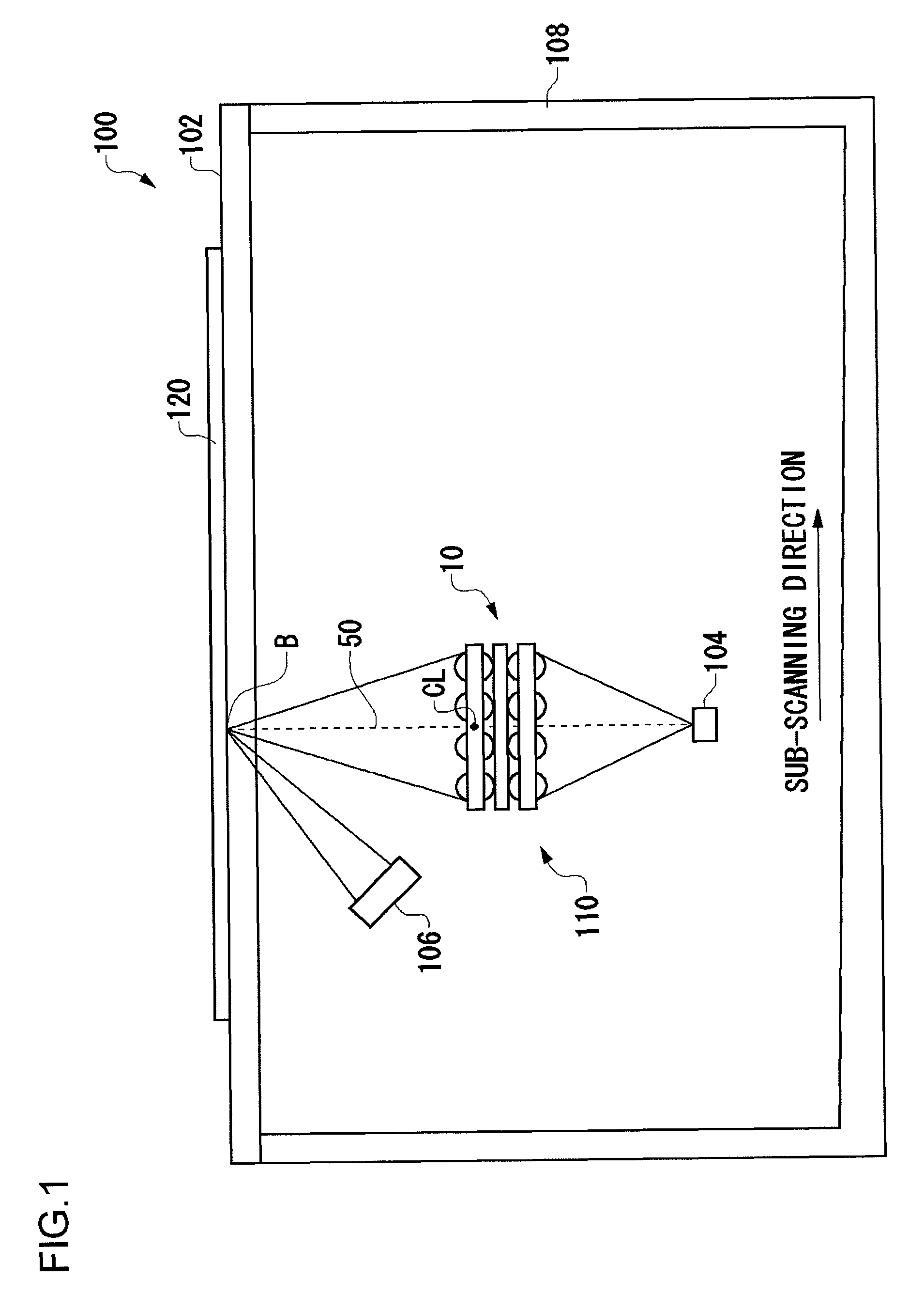
[0032]FIG. 1 shows the schematic structure of an image reading device 100 using an erecting equal-magnification lens array plate 10 according to an embodiment of the present invention. An erecting equal-magnification imaging optical system 110 is housed inside a housing 108 of the image reading device 100. The erecting equal-magnification imaging optical system 110 is provided with a line light source 106, an erecting equal-magnification lens array plate 10, and a line image sensor 104.

[0033]The line light source 106 is a light source emitting a substantially straight light. The term “substantially straight” encompasses straight lines having a width of about 200 μm, or curves or staggered lines not exceeding a width of about 200 μm. The light exiting the line light source 106 irradiates a document 120 pl...


PUM


Abstract

An erecting equal-magnification lens array plate includes a stack of a plurality lens array plates built such that pairs of corresponding lenses form a coaxial lens system, where each lens array plate is formed with a plurality of convex lenses on both surfaces of the plate. The plate receives light from a substantially straight light source facing one side of the plate, and the plate forms an erect equal-magnification image of the substantially straight light source on an image plane facing the other side of the plate. The main lens arrangement direction differs from the main scanning direction of the erecting equal-magnification lens array plate. The erecting equal-magnification lens array plate is provided with a first light shielding member operative to shield light not contributing to imaging and formed in the neighborhood of a position in the intermediate plane in the erecting equal-magnification lens array plate where an inverted image of the substantially straight light source is formed, and with a second light shielding member operative to reduce the amount of light incident on at least some of the lenses at the periphery in the sub-scanning direction and provided on a lens surface facing a light source.

Description

BACKGROUND OF THE INVENTION[0001]1. Field of the Invention[0002]The present invention relates to an erecting equal-magnification lens array plate used in image reading devices and image forming devices.[0003]2. Description of the Related Art[0004]Some image reading devices such as scanners and image forming devices such as LED printers are known to use erecting equal-magnification optical systems. Erecting equal-magnification optical systems are capable of reducing the size of devices better than reduction optical systems. In the case of image reading devices, an erecting equal-magnification optical system comprises a line light source, an erecting equal-magnification lens array, and a line image sensor. In the case of image forming devices, an erecting equal-magnification optical system comprises a line light source, an erecting equal-magnification lens array, and a photosensitive drum.[0005]A rod lens array capable of forming an erect equal-magnification image is used as an erecti...

Claims


Application Information

Patent Timeline
Patent Type & Authority Patents(United States)
IPC IPC(8): G02B27/10
CPCH04N1/0311H04N1/0312G02B3/0006H04N2201/02497
Inventor SHIMMO, KATSUHIDENAGATA, HIDESHI
Owner NIPPON SHEET GLASS CO LTD
Why Eureka
Try Eureka