Apparatus and methods for resizing electronic displays

a technology of electronic displays and apparatuses, applied in the field of electronic displays, can solve the problems of affecting the operation of the display, the physical size and/or shape of the display, and the inability to modify without disturbing the surrounding instruments, etc., and achieve the effects of enhancing the functionality of the display, reducing the physical size and/or shape, and enhancing the functionality

Inactive Publication Date: 2010-08-24
PIXEL SCI
View PDF35 Cites 15 Cited by
  • Summary
  • Abstract
  • Description
  • Claims
  • Application Information

AI Technical Summary

Benefits of technology

[0010]The present invention involves systems and methods for modifying a COTS display, e.g., by changing the physical size and / or shape of the COTS display to meet the requirements of a target application. This may be accomplished by cutting the COTS display to reduce its physical size and / or shape, and then resealing the display to achieve the desired performance. The basic functionality of the COTS display may remain intact, that is, the customized display may have a new size and / or shape, and may have altered electronic drivers, image-generating media, rearranged electronics, additional seals, additional films, etc. Optionally, the resized display may have enhanced functionality. However, the customized display should be able to operate in a target application designed to interface with a display of the same type (e.g., LCD) as the original (e.g., COTS) display.
[0011]When the plates are cut, internal electronics may also be cut, often requiring reestablishment of electrical continuity. Similarly, the display electronics may be removed, reattached, and / or otherwise modified, and filters, polarizers, and / or other films associated with the display may be cut, e.g., to conform to the customized display size and / or shape. Thus, the opportunity exists to add enhanced functionality to the display. Optionally, a custom bezel and / or frame may then be used to house the display, e.g., allowing for additional ruggedization of the entire unit.
[0012]To reseal the display, an adhesive is applied along at least the cut edge or edges, e.g., between the plates of the display along the cut edge(s). Optionally, a second seal may be added to minimize penetration of humidity and other contaminants into the display medium (e.g., liquid crystal material) inside the display cell. A third seal, e.g., serving as a mask, may also be applied to prevent light, such as that used to back-light LCDs, from passing through the display's outer edges.
[0013]Electronic drivers, typically VLSI circuits (bonded to TAB substrates attached to the display, or attached directly to the display as COG) may be added, repositioned and / or reattached as needed, and the circuitry on the display plates may be altered to make electrical connection to the new VLSI circuits. Filters, films, polarizers, etc. may then be cut and / or installed as desired, and additional components such as heaters, optical elements, infrared filters, touch panels, transducers, etc., may be added to alter and / or enhance durability or functionality of the display.

Problems solved by technology

Typically, the displays and their associated bezels (face plates) and frames (interfacing and supporting hardware) are built to demanding specifications for durability, reliability, and operating life, e.g., based upon industry requirements, and the resulting displays may have relatively complex electrical, chemical, optical, and / or physical characteristics.
Due to the high costs associated with such varying and demanding specifications, for any particular application, it is thus economically desirable for manufacturers to produce a common design in high production volume, resulting in COTS displays all having substantially the same characteristics and a limited number of physical sizes.
For most applications, however, such modifications cannot be made without disturbing the surrounding instruments, controls, and displays already incorporated into the control panel.
Even if the appropriate modifications could be made, they are typically cost-prohibitive.

Method used


Image

  • Apparatus and methods for resizing electronic displays
  • Apparatus and methods for resizing electronic displays
  • Apparatus and methods for resizing electronic displays

Examples


Embodiment Construction

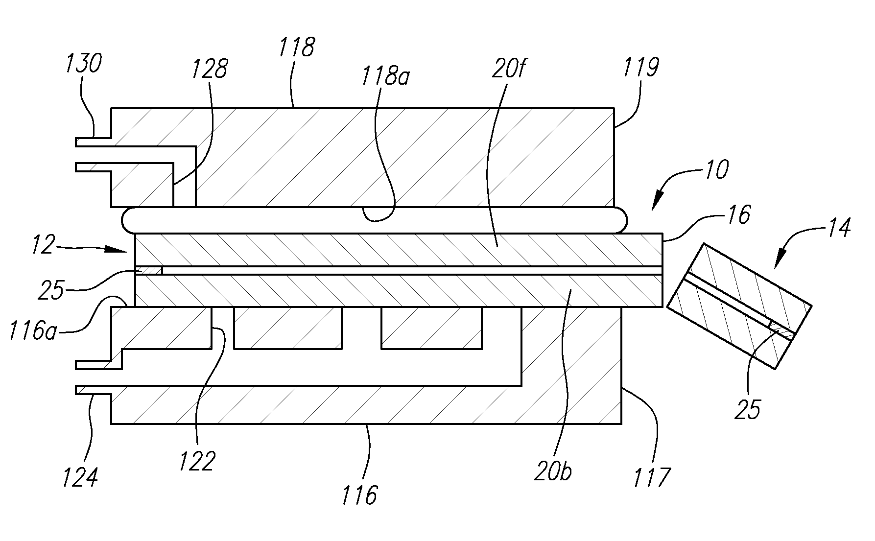
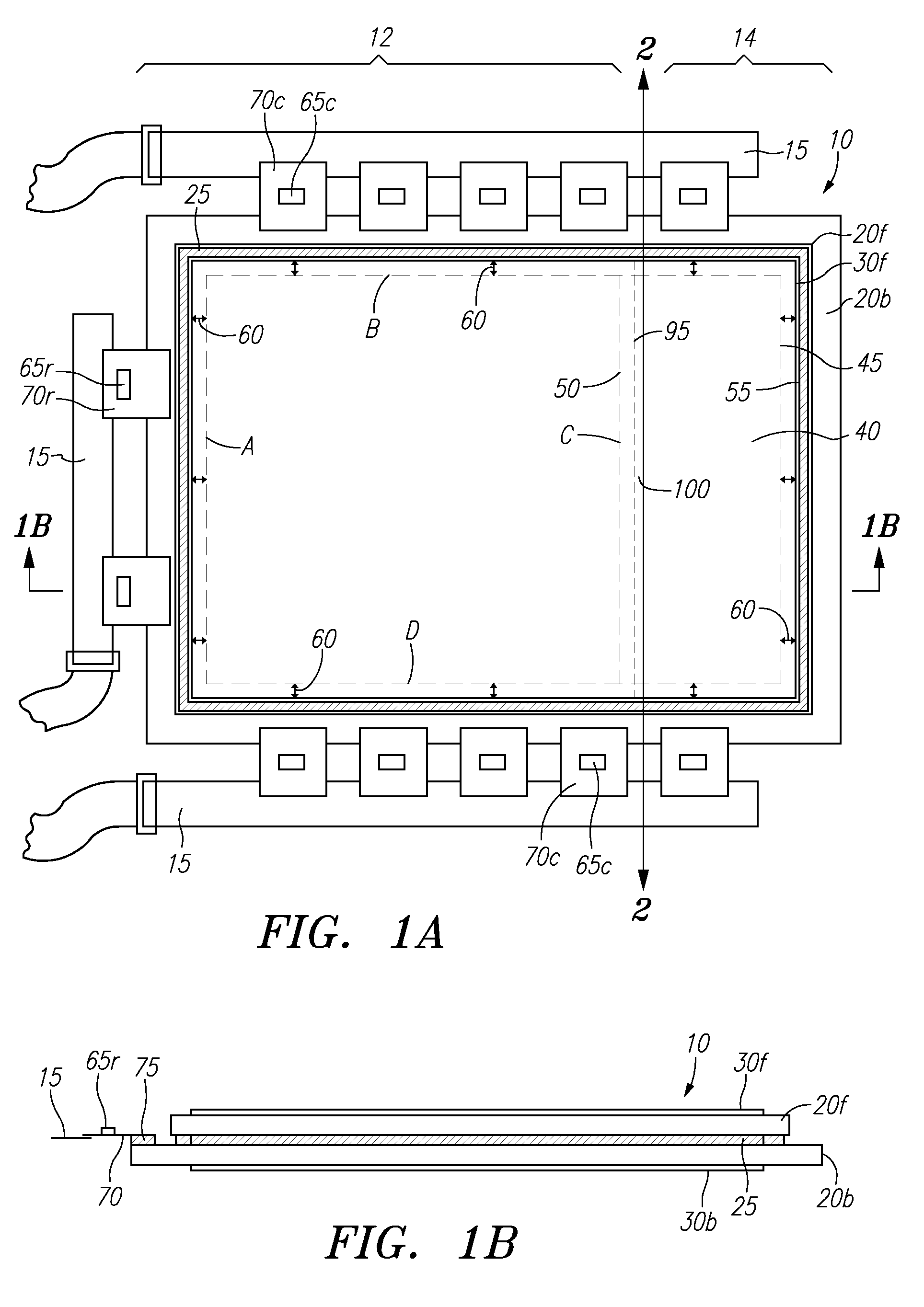
[0030]Turning to the drawings, FIGS. 1A and 1B show a typical non-square COTS AMLCD 10, e.g., before resizing and / or other modification as described herein, but after disassembly from its original bezel, frame, and other associated hardware and electronics. For clarity, some of the external components associated with the display 10 (other than the circuit boards 15) are not shown, e.g., that may be bonded or otherwise attached to the display plates 20f and 20b. Such external components may be removed before or while customizing the display 10, as described elsewhere herein.

[0031]The display 10 generally includes a front plate 20f and a back plate 20b, e.g., made of glass or plastic, such as borosilicate or other hard glass. The plates 20 are held together by a perimeter seal 25, and may be further secured within a bezel (not shown), which, in turn, may be secured to a frame or other hardware (not shown), e.g., for attachment to the target location, e.g., in a cockpit panel of an air...


PUM

PropertyMeasurementUnit
pressureaaaaaaaaaa
pressureaaaaaaaaaa
distanceaaaaaaaaaa

Abstract

Apparatus and methods for resizing COTS AMLCDs or other electronic displays, as well as resized displays made using these apparatus and methods, are provided. The electronic display includes a front plate, a back plate, a perimeter seal spacing the front and back plates apart, and image-generating medium contained in an area between the front and back plates. A target portion of the display may be identified and separated from an excess portion of the display, e.g., by cutting and breaking the plates of the display, thereby creating an exposed edge along the target portion. The plates of the target portion are pressed towards one another, e.g., to stabilize or compress the target portion. An adhesive is applied to the exposed edge, and the pressure is released to draw the adhesive between the plates along the exposed edge.

Description

FIELD OF THE INVENTION[0001]The present invention relates generally to electronic displays, and more particularly to apparatus and methods for modifying electronic displays, e.g., to customize, resize, and / or ruggedize an original display, and to displays manufactured using such apparatus and methods.DEFINITIONS[0002]In this application, COTS is an acronym for “Commercial Off-The-Shelf,” FPD is an acronym for “Flat-Panel Display,” LCD is an acronym for “Liquid Crystal Display,” PDLC is an acronym for “Polymer-Dispersed Liquid Crystal,” AMLCD is an acronym for “Active Matrix Liquid Crystal Display,” TAB is an acronym for “Tape-Automated-Bonding,” COG is an acronym for “Chip-On-Glass,” UV is an acronym for “ultraviolet,” VLSI is an acronym for “Very Large Scale Integration,” and HDTV is an acronym for “High-Definition Television.”BACKGROUND[0003]Electronic displays are commonly used to portray data, e.g., in the form of visual text and / or other images, so the data may be interpreted a...

Claims


Application Information

Patent Timeline
Patent Type & Authority Patents(United States)
IPC IPC(8): H01J9/00G02F1/1341G02F1/1339
CPCG02F1/133351G02F1/1309G02F1/1341G02F1/1303G02F1/133615G02F1/1316
Inventor TANNAS, JR., LAWRENCE E.
Owner PIXEL SCI
Why Eureka
Try Eureka