Central frequency adjustment device and adjustable inductor layout using trimmable wire

a technology of inductor layout and central frequency adjustment, which is applied in the direction of resonant circuit details, inductance/transformer/magnet manufacture, continuous tuning, etc., can solve the problems of reducing circuit performance, reducing the q factor of the lc tank, and reducing the method. the effect of reducing the central frequency without reducing the q factor

Active Publication Date: 2010-08-24
REALTEK SEMICON CORP
View PDF4 Cites 0 Cited by
  • Summary
  • Abstract
  • Description
  • Claims
  • Application Information

AI Technical Summary

Benefits of technology

[0010]In view of the above, the present invention provides a central frequency adjustment device and adjustable inductor layout in which the central frequency adjustment device of the present invention is provided with the advantages of reducing the central frequency without reducing the Q factor. Furthermore, the adjustable inductor layout of the present invention is not only provided with the advantage of a reduction in the central frequency without reducing the Q factor, but also the layout method does not increase the layout area. Thus, the method provides the advantage of saving layout area, improving the conventional layout method. Furthermore, the central frequency adjustment device of the present invention includes a cut-off capacitor, which can both reduce and increase the central frequency without causing a reduction of the Q factor.

Problems solved by technology

However, this method works only when an increase of the central frequency is required.
The shortcoming of this method is that switch A10 will also generate parasitic resistance, which reduces the Q factor of the LC tank, and further reduces the circuit performance.
It may be seen from the preceding, therefore, that adjustment of the Q factor is an important issue.

Method used


Image

  • Central frequency adjustment device and adjustable inductor layout using trimmable wire
  • Central frequency adjustment device and adjustable inductor layout using trimmable wire
  • Central frequency adjustment device and adjustable inductor layout using trimmable wire

Examples


first embodiment

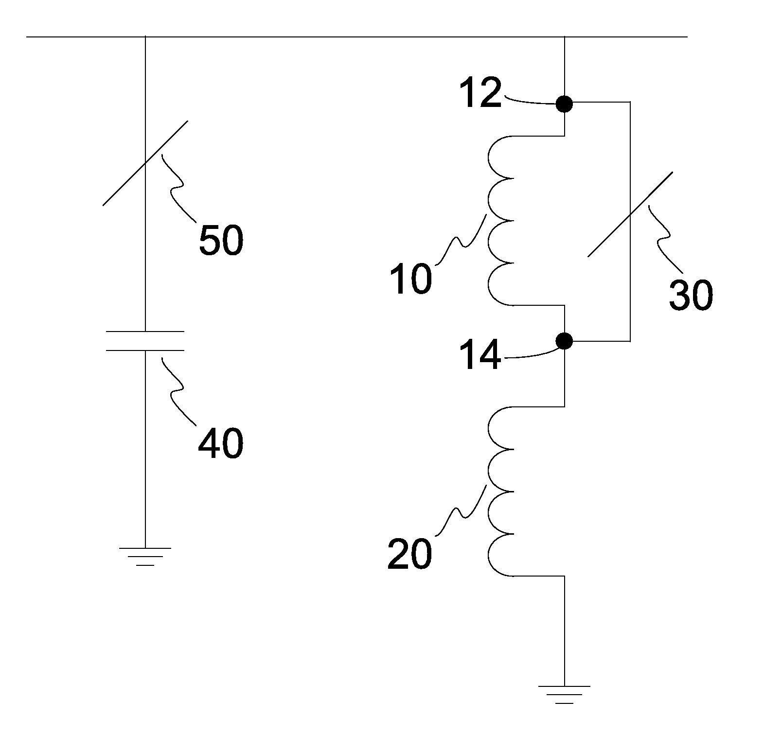
[0022]Please refer to FIG. 2, which is a central frequency adjustment device for adjusting the central frequency of LC tank as the present invention. As shown in FIG. 2, the central frequency adjustment device includes a first inductor 10, a second inductor 20, and a first trimmable wire 30.

[0023]The first inductor 10 includes a first end 12 and a second end 14. One end of the second inductor 20 is coupled with the second end 14 of the first inductor 10, while the other end of the second inductor 20 is coupled with another terminal. The present embodiment represents the terminal as grounding, but is not limited to it. The first trimmable wire 30 is connected to the first inductor 10 in parallel, and to the second inductor 20 in series for short-circuiting the first inductor 10 by cutting off the first trimmable wire 30 to adjust the central frequency.

[0024]The process of circuit fabrication suffers unavoidably from errors, so that the central frequency is somewhat offset from the id...

second embodiment

[0031]The central frequency adjustment device of the second embodiment could adjust the central frequency by cutting off the first trimmable wire 30 or the second trimmable wire 50. When cutting off the first trimmable wire 30, the short-circuit status of the first inductor 10 originally in short-circuit is removed, and the overall inductance is increased with the inductance of the first inductor 10 from the original inductance of the second inductor 20 only. Thus, the overall inductance is increased, and the central frequency is reduced. Therefore, the central frequency of the LC tank is reduced by cutting off the first trimmable wire 30.

[0032]When the second trimmable wire 50 is cut off, because the second trimmable wire 50 is connected to capacitor 40 in series, the cutting of the second trimmable wire 50 isolates capacitor 40, so that the capacitance generated in capacitor 40 is removed. Thus, the cutting of the second trimmable wire 50 reduces the capacitance, and further incre...


PUM


Abstract

The present invention provides a central frequency adjustment device and adjustable inductor layout; wherein, the central frequency adjustment device is applied in an inductor / capacitor tank (LC tank) for adjusting the central frequency of the LC tank. The device comprises a first inductor with a first end and a second end; a second inductor with one end coupled with the second end of the first inductor; and, a first trimmable wire connected to the first inductor in parallel and to the second inductor in series, which adjusts the central frequency by cutting off the first trimmable wire.

Description

CROSS-REFERENCES TO RELATED APPLICATIONS[0001]This non-provisional application claims priority under 35 U.S.C. §119(a) on Patent Application No(s). 096103303 filed in Taiwan, R.O.C. on Jan. 30, 2007, the entire contents of which are hereby incorporated by reference.FIELD OF INVENTION[0002]The present invention relates to a central frequency adjustment device and adjustable inductor layout, and particularly a central frequency adjustment device and adjustable inductor layout without reducing the Q factor or increasing the layout area.BACKGROUND[0003]The inductor / capacitor tank circuit (hereinafter “LC tank”) could be applied in various circuits, for example: a modulator, a Voltage Controlled Oscillator (VCO), etc. The central frequency (f) of an LC tank could be represented by the formula[0004]f=12⁢⁢π⁢LC.In order to overcome the central frequency offset from the ideal value of the design, adjustment of the capacitance (C) or the inductance (L) is required. Conventionally, there are t...

Claims


Application Information

Patent Timeline
Patent Type & Authority Patents(United States)
IPC IPC(8): H03J3/22
CPCH01F41/045H03J1/00H01F17/0006H03J2200/15
Inventor LIU, REN CHIEH
Owner REALTEK SEMICON CORP
Why Eureka
Try Eureka