Performance visualization system

a performance visualization and system technology, applied in multi-objective optimisation, instruments, cad techniques, etc., can solve the problems of interrelated performance of paths connected with the same register, and the performance of another path between these registers may get wors

Inactive Publication Date: 2010-08-24
ALTERA CORP
View PDF5 Cites 19 Cited by
  • Summary
  • Abstract
  • Description
  • Claims
  • Application Information

AI Technical Summary

Benefits of technology

[0007]An embodiment of the invention displays user designs and performance information at different levels of detail. Related register bits are combined into a metaregister and displayed as a graph node. The set of paths and associated combinatorial logic between two or more metaregisters are collapsed into a metapath and displayed as a graph connection. The set of paths associated with a metapath can be selectively revealed in response to user input. Metapaths can be annotated with performance information of its associated paths, such as timing, area, and power consumption information. The annotated performance information can represent performance information of one or more paths or aggregate attributes of the set of paths. Paths associated with control signals and finite state machines can be identified and displayed as separate graph connections.

Problems solved by technology

However, the performance of paths connected with the same registers often are interrelated.
Thus, when a designer improves the performance, such as the timing, of one path between registers, the performance of another path between these registers may get worse.
In these situations, the designer merely shifts a problem to different paths, rather than finding a solution that improves the performance of the overall design.
This problem can occur in any type of integrated circuit design and is especially frequent with programmable devices such as field programmable gate arrays, which route all of the paths between source and destination registers independently.

Method used


Image

  • Performance visualization system
  • Performance visualization system
  • Performance visualization system

Examples


Embodiment Construction

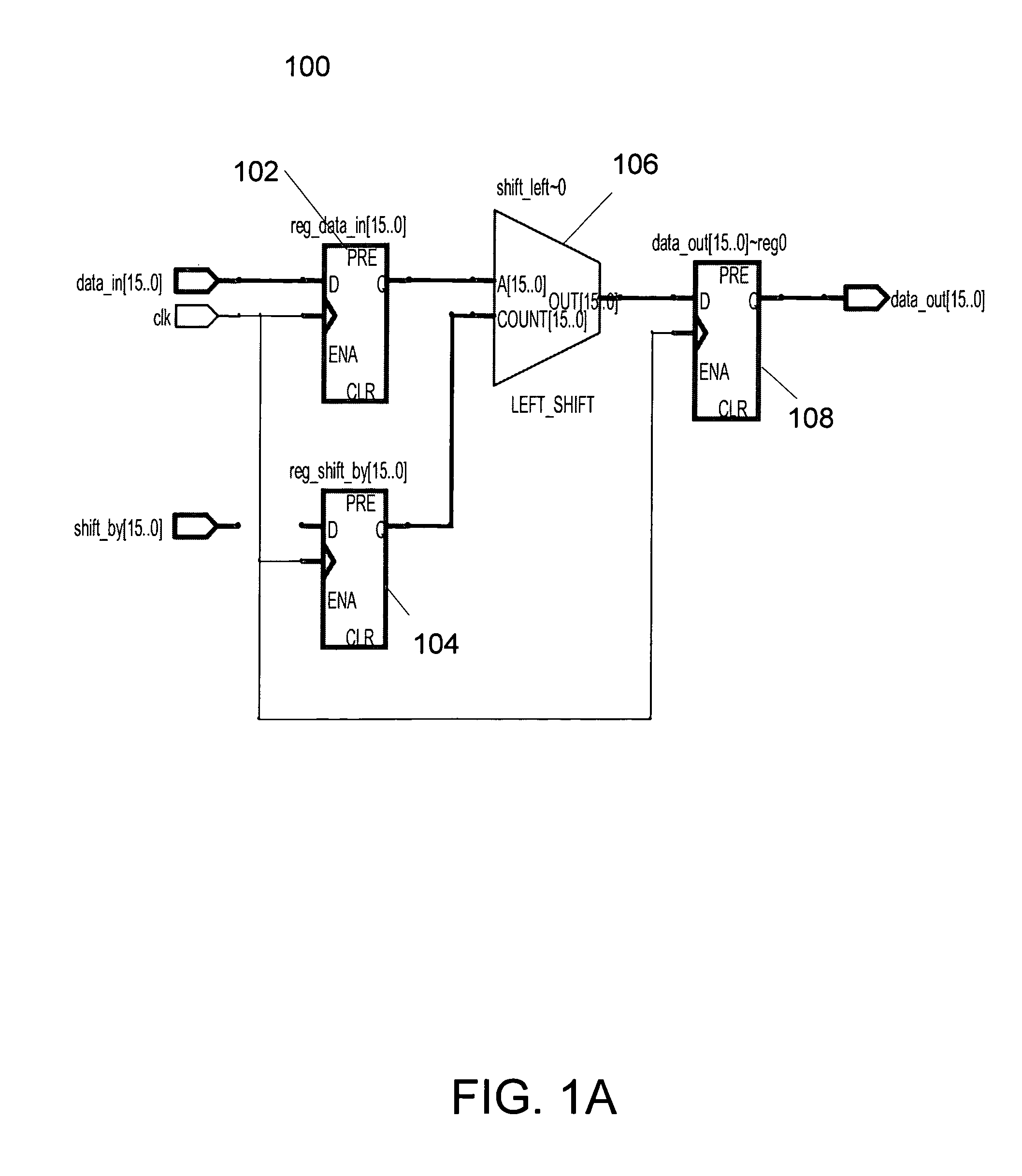
[0021]FIG. 1A illustrates an example circuit design 100. Design 100 is a 16-bit barrel shifter. Design 100 is capable of storing a 16 bit input value in register 102 and 16-bit shift value in register 104. In response to the shift value in register 104, a shift unit 106 shifts the value in register 102 to the left by the shift value in register 104 and stores the result in 16-bit register 108.

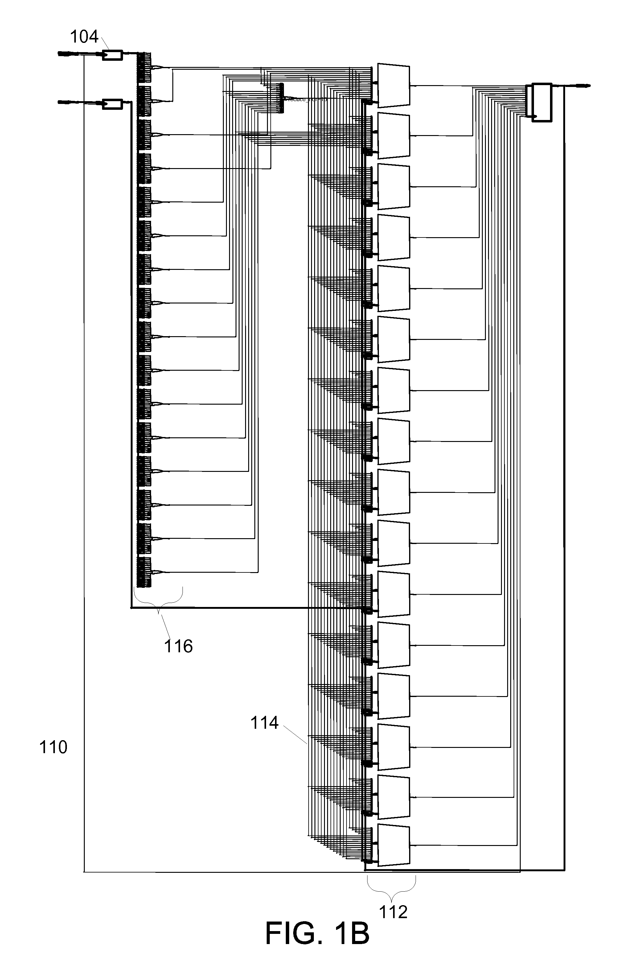
[0022]FIG. 1B illustrates schematic 110 of design 100. Schematic 110 shows that the shift unit 108 is comprised of a set of multiplexers 112. In schematic 110, the output of the shift value register 104 is connected by sets of combinatorial logic 116 with the select inputs of the set of multiplexers 112. As can be seen in schematic 110, the set of paths 114 between the sets of combinatorial logic 116 and the set of multiplexers 112 is large and complicated.

[0023]FIG. 1C illustrates an example display 130 of a prior performance visualization application showing design 100. In example display 130...


PUM


Abstract

A visualization displays user designs and performance information at different levels of detail. Related register bits are combined into a metaregister and displayed as a graph node. The set of paths and associated combinatorial logic between two or more metaregisters are collapsed into a metapath and displayed as a graph connection. The set of paths associated with a metapath can be selectively revealed in response to user input. Metapaths can be annotated with performance information of its associated paths, such as timing, area, and power consumption information. The annotated performance information can represent performance information of one or more paths or aggregate attributes of the set of paths. Paths associated with control signals and finite state machines can be identified and displayed as separate graph connections.

Description

BACKGROUND OF THE INVENTION[0001]The present invention relates to the field of software for designing integrated circuits. A typical design cycle for an integrated circuit, referred to as compilation, starts with an extraction phase, followed by a logic synthesis phase, and, depending upon the target hardware architecture, either a layout phase or fitting and assembly phases.[0002]In addition to implementing their desired functions, designs typically must satisfy one or more additional design goals, such as operating speed, power consumption, and / or programmable device resource consumption. Typically, the predicted performance of a design with respect to one or more design goals is determined through simulation or analysis following a phase of the compilation. The designer can evaluate the predicted performance of the design and decide to either accept the results of the compilation or modify the design to improve its predicted performance, and hopefully its actual performance as we...

Claims


Application Information

Patent Timeline
Patent Type & Authority Patents(United States)
IPC IPC(8): G06F17/50
CPCG06F17/505G06F17/5054G06F2217/08G06F2217/78G06F2217/84G06F30/327G06F30/34G06F2111/06G06F2119/12G06F2119/06G06F30/33G06F30/31
Inventor HUTTON, MICHAEL D.KARCHMER, DAVIDZHANG, ZHIRU
Owner ALTERA CORP
Why Eureka
Try Eureka