
Method and blade repair element for blisk repair or new blisk manufacture

a technology for blisks and blades, applied in manufacturing tools, machines/engines, forging/pressing/hammering apparatus, etc., can solve the problems of affecting the leading edge of the blade is liable to damage by larger objects, and the compression blade of the aircraft engine is subject to considerable erosion. , to achieve the effect of ensuring the longevity of the repaired blisk or blisk drum

Inactive Publication Date: 2010-08-31
ROLLS ROYCE DEUT LTD & CO KG
View PDF28 Cites 4 Cited by
  • Summary
  • Abstract
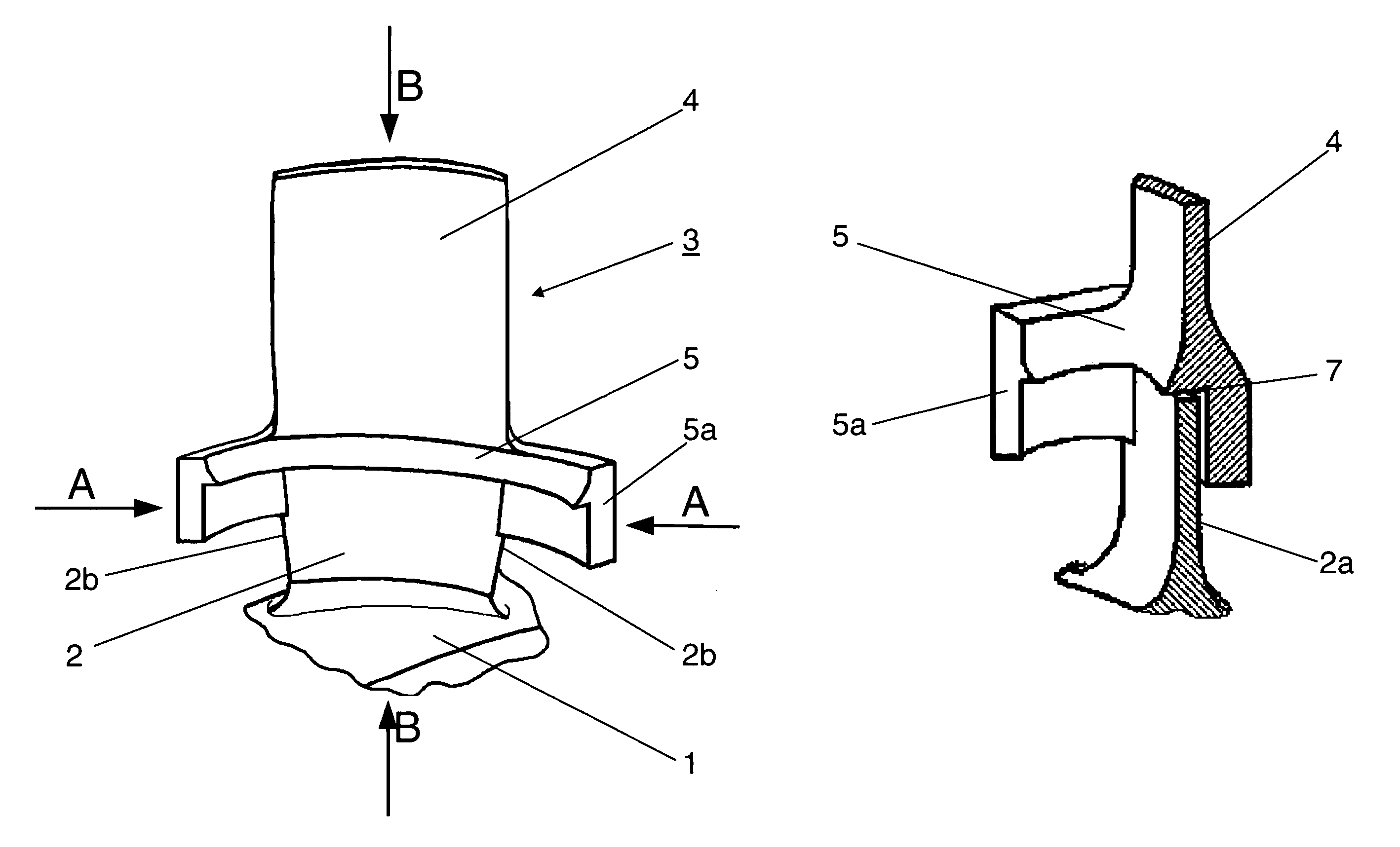
  • Description
  • Claims
  • Application Information

AI Technical Summary

Benefits of technology

[0006]In a broad aspect, the present invention provides for a reduction of the work effort and costs for blisk repair, and for an appropriate method and means for the performance of this method, with this method also being applicable to the new manufacture of blisks.
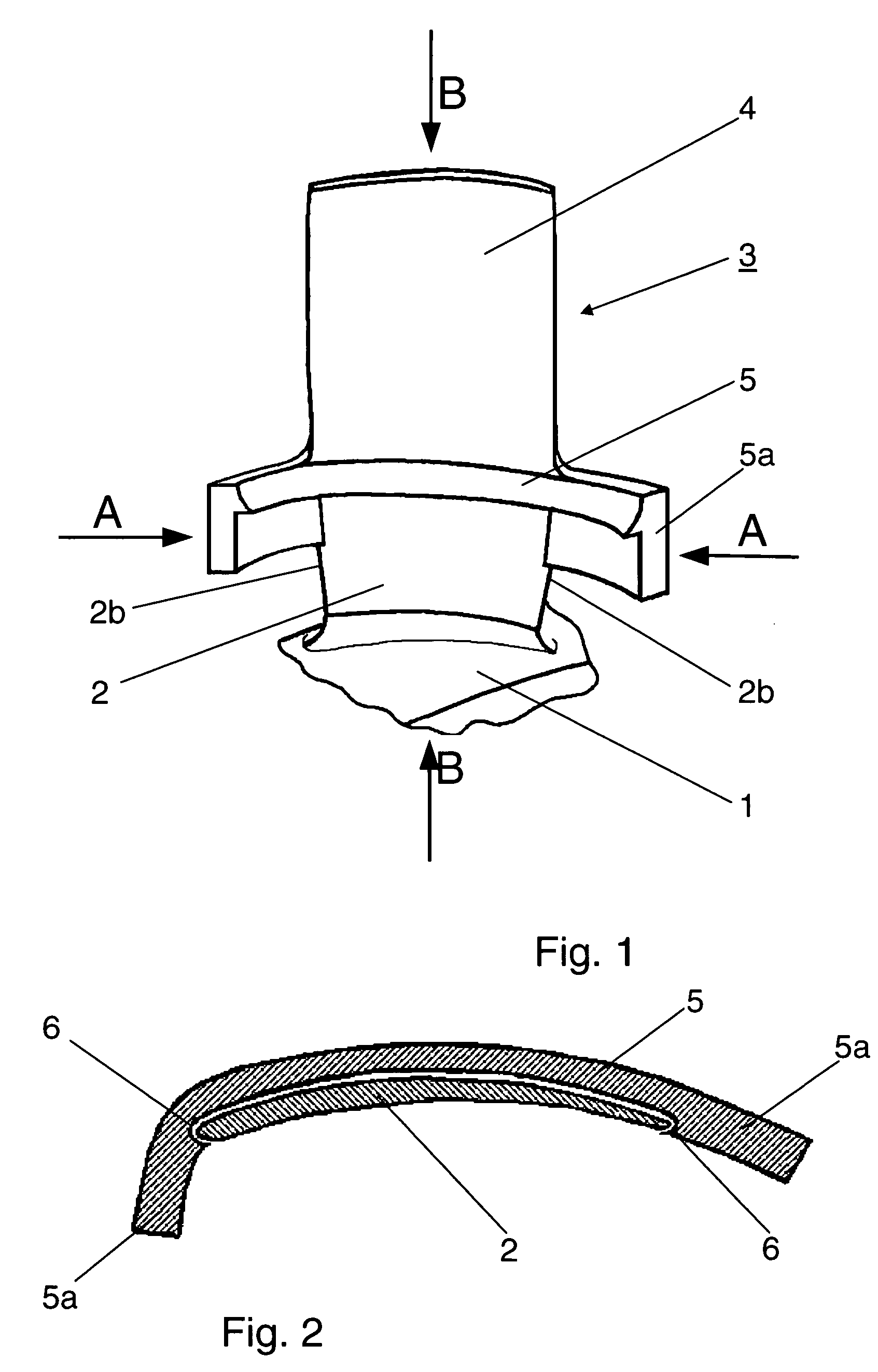
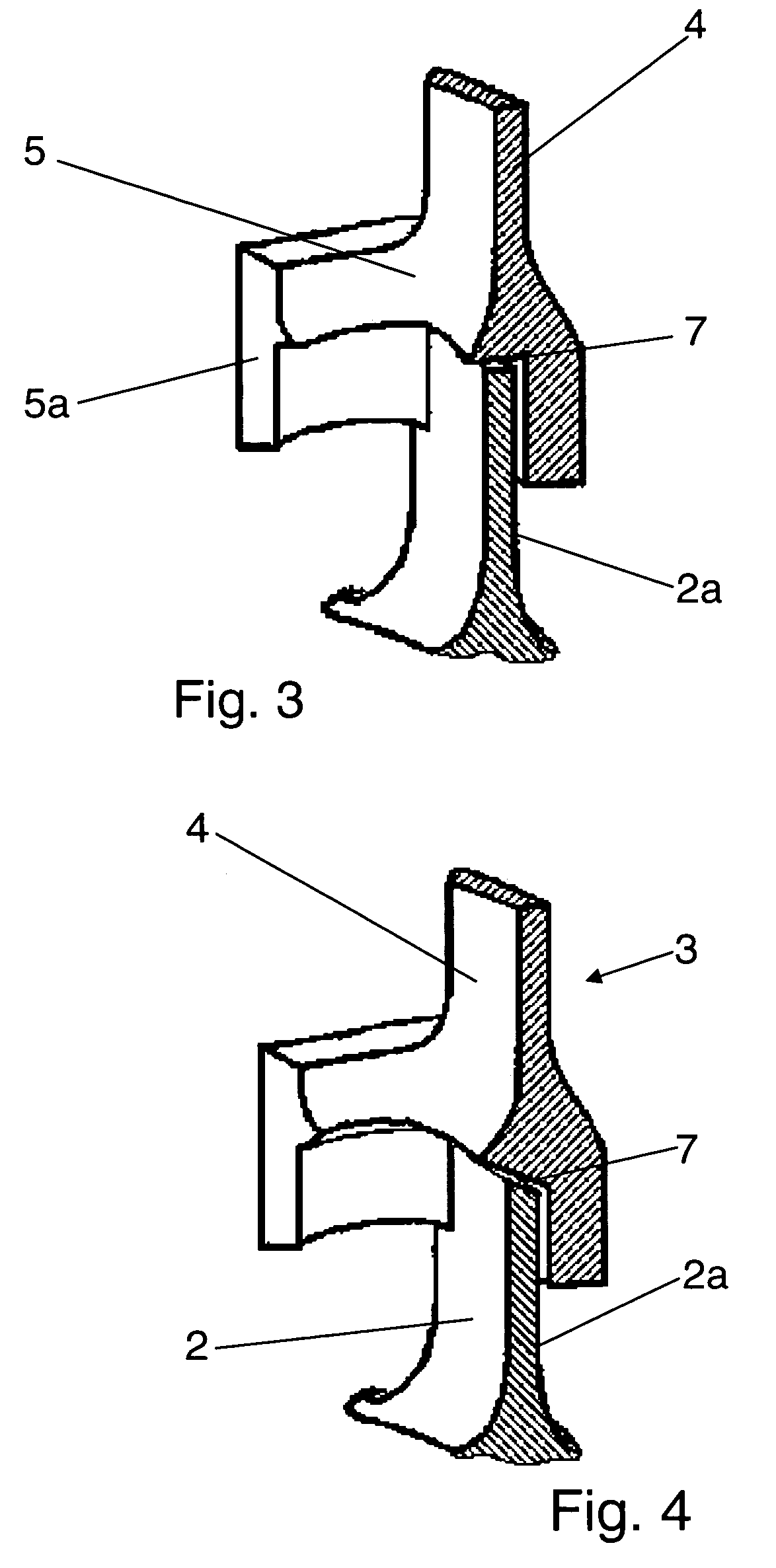
[0008]The essential idea of the present invention is that the damaged airfoils are completely cut off above the blade root with the exception of a stump, actually in a specific, vibration-free or low-vibration area along a nodal line determined beforehand for the respective type of blade. The known size of the removed blade section will be used for the pre-manufacture of standardized blade repair elements, these comprising a new blade portion of the shape and size known from the removed blade section which is one piece with a fixation means provided at the side of the new blade portion intended for attachment to the free end face of the blade stump. By means of this fixation means, the new blade portion is accurately positioned and clamped on the blade root under formation of a welding gap, and then machine-welded to the blade root. Subsequently, the integral fixation means is removed in a cutting or non-cutting process.
[0009]The use of pre-manufactured, standardized blade repair elements that can easily be clamped in position, provides for the efficiency and inexpensiveness of the proposed repair method, while the standardized pre-manufacture of these elements, as well as the production of the joint in the vibration-free nodal line, ensure the longevity of the repaired blisk or blisk drum. Owing to the stiffening function of the fixation means, the thin-walled airfoil will be stressed mechanically to only an insignificant extent during machining. For the above reasons, the inspection effort after blisk repair will also be considerably lower for the present method than for other known methods.
[0010]Similarly, the above repair method can efficiently be applied to the new manufacture of single or multi-stage blisks in that disks with integral blade stumps are initially produced such that their faying end face lies in the area of a vibration-free nodal line of the entire airfoil. Subsequently, these blade stumps are joined, in the above manner, to the standardized, pre-manufactured blade (repair) elements, which can equally be used for blade repair.
[0011]The blade repair elements (or the similarly designed blade assembly elements for blisk new manufacture) consist of a new blade portion that is identical in shape and size with the cut off (or still missing) blade section, and form one part with a rigid ledge provided for fixation and stabilization at that side of the new blade portion that is to be joined to the blade stump. This ledge holds the new blade portion positively and accurately in position on the blade stump during subsequent processing by welding and milling, enabling machining to be performed.

Problems solved by technology

The compressor blades of aircraft engines are, as is generally known, subject to considerable erosion in the area of the tip edge and—if the sand particle content of the air is high—also in a zone reaching from the tip edge to the trailing edge.
Moreover, the blade leading edge, in particular, is liable to damage by larger objects, but also by small stones.
This advantageous, but expensive, approach is not possible with compressors in blisk technology as their rotor blades are one piece with the rotor disk.
The repair of blisks by cutting off and either subsequent multi-pass welding or individual manufacture of the corresponding insert and correct manual positioning and fixation of the latter in the limited space available between the blades incurs considerable effort.
In addition, the effort for technical assessment of the quality of the repaired blades or blisks is high.

Method used


Image

  • Method and blade repair element for blisk repair or new blisk manufacture
  • Method and blade repair element for blisk repair or new blisk manufacture
  • Method and blade repair element for blisk repair or new blisk manufacture

Examples


Embodiment Construction

[0017]In accordance with the present repair method, the worn or damaged blade sections of a single or multi-stage blisk used, for example, in a compressor, are cut off over the entire width of the blade such that a blade stump 2 is left on the disk 1 of the blisk, this stump forming one piece with the disk. Beforehand, vibration investigations are performed on the blades allocated to the respective compressor stage to determine the minimum vibration area across the blade width for the respective blade type. It was found that the nodal lines for low vibrations and, thus, low material stress extend, among others, in an area located slightly above the blade root and extending essentially over the entire blade width. This is exactly the area where the damaged blade is cut off and the free edge of the blade stump 2 left for subsequent welding is located. Obviously, the height of the stump can vary on a multi-stage blisk (blisk drum) with different blades in the individual stages. It is a...


PUM

PropertyMeasurementUnit
shapeaaaaaaaaaa
sizeaaaaaaaaaa
widthaaaaaaaaaa

Abstract

In the repair of a blisk or blisk drum, the damaged airfoils are completely cut off a low-stress nodal line of the respective blade, except for a blade stump (2), and are each replaced by a new blade repair element (3) of a same shape and size which is accurately clamped onto the blade root by a ledge (5) formed onto its mating end, with this ledge (5) also serving for fixation of the processing fixtures and stabilization of the thin airfoil, and is then welded to the blade root and subsequently subjected to a cutting or non-cutting operation for removal of the ledge (5). This highly efficient repair method can similarly also be applied to the new manufacture of blisks.

Description

[0001]This application claims priority to German Patent Application DE102004032461.1 filed Jun. 30, 2004, the entirety of which is incorporated by reference herein.BACKGROUND OF THE INVENTION[0002]This invention relates to a method for the repair of blisks in which the damaged blade section is removed and replaced by a new blade portion of corresponding shape and size by welding, and to a blade repair element for the performance of the method. Moreover, the present invention relates to the new manufacture of blisks.[0003]The compressors of aircraft engines are, in many cases, designed in blisk technology, with the rotor blades being integral with the rotor disk. In comparison with compressors whose blades are separately manufactured and separably attached to the rotor disk, the one-piece blisks are advantageous in that they are capable of withstanding higher mechanical loads. This has positive consequences, for example on the weight and the performance of the engine.[0004]The compre...

Claims


Application Information

Patent Timeline
Patent Type & Authority Patents(United States)
IPC IPC(8): B23P6/00
CPCB23K26/422B23P6/005B23P15/006F01D5/34F01D5/005Y10T29/49318Y10T29/49336Y10T29/4932B23K26/702
Inventor MIELKE, RAINERJOHANN, ERIK
Owner ROLLS ROYCE DEUT LTD & CO KG
Learn More