Steering gear

a technology of steering gear and auxiliary support, which is applied in the direction of gearmaking, mechanical equipment, transportation and packaging, etc., can solve the problems of only statically over-determination of the mounting position of the steering rack, no longer being able to rotate the auxiliary support about the steering rack axis, and not being able to permanently mount the steering rack, etc., to achieve easy production, easy to optimize, and easy to fit quickly and easily

Active Publication Date: 2010-08-31
TRW AUTOMOTIVE GMBH
View PDF18 Cites 15 Cited by
  • Summary
  • Abstract
  • Description
  • Claims
  • Application Information

AI Technical Summary

Benefits of technology

[0008]In order to achieve this feature, the invention provides a steering gear for a rack and pinion steering system, comprising a housing in which a steering rack is guided for displacement along its axis, and an auxiliary support which is located at an axial end of the housing, the auxiliary support limiting a bending of the steering rack. This offers the advantage that a steering rack having a smaller diameter can be used, and so on the one hand the weight, and on the other hand the cost of the steering gear are reduced. It should be emphasized here that, despite the auxiliary support, tensions rising from statically over-determinate mounting do not play a role because the steering rack remains mounted in a largely statically determinate manner. Indeed, the auxiliary support is not a permanent mounting, but only offers a temporary support in the case of extreme bending loads. The mounting of the steering rack is therefore only statically over-determinate during the short period of extreme loading. Moreover, the auxiliary support makes it possible to use smaller serrated modules (and so a smaller serration height). This increases the cross-section of the steering rack and offers advantages with regard to the design of the serrations.
[0012]Preferably, the auxiliary support is a clip with a C-shaped cross-section. This type of clip is easy to produce and can be fitted quickly and easily on the housing.
[0013]Furthermore, it is possible to make the auxiliary support from a synthetic material. The auxiliary support is thus particularly inexpensive, and due to the synthetic composition, it is easy to optimize with regard to elasticity and slide properties.

Problems solved by technology

Indeed, the auxiliary support is not a permanent mounting, but only offers a temporary support in the case of extreme bending loads.
The mounting of the steering rack is therefore only statically over-determinate during the short period of extreme loading.
Due to this protrusion, it is no longer possible to rotate the auxiliary support about the steering rack axis relative to the housing.

Method used


Image

  • Steering gear
  • Steering gear
  • Steering gear

Examples


Embodiment Construction

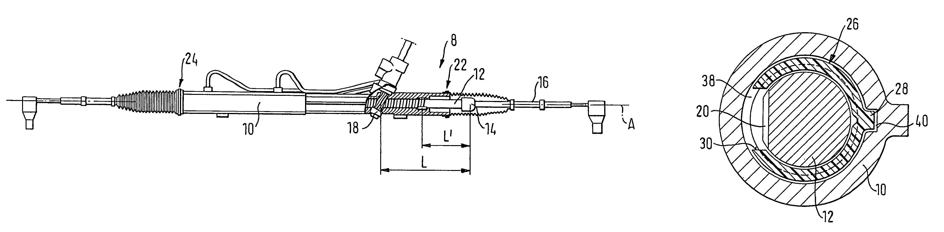
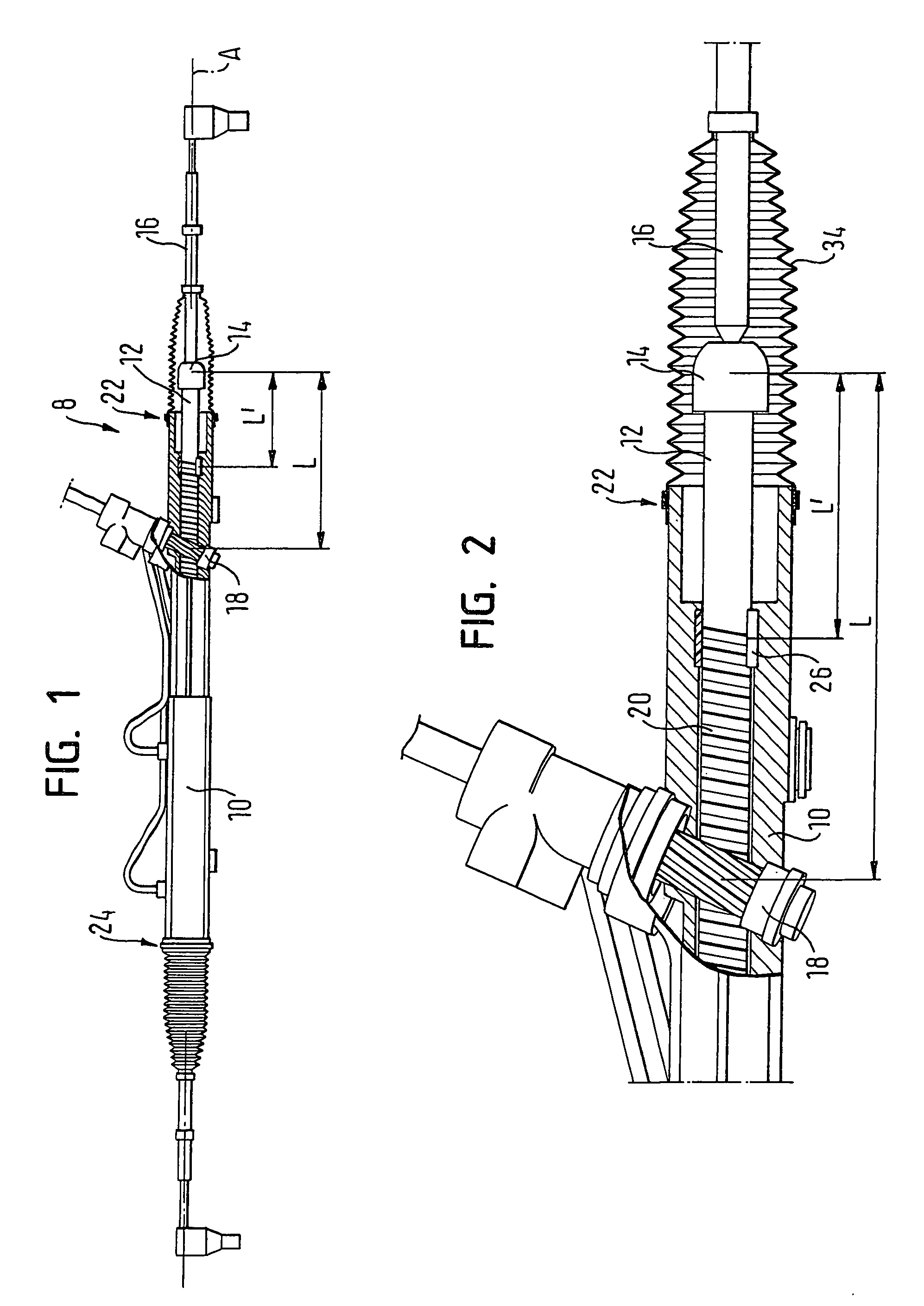
[0022]FIG. 1 shows a steering gear 8 for a rack and pinion steering system, comprising a housing 10 in which a steering rack 12 is guided for displacement along its axis A. The steering rack 12 projects out of the housing 10 at its axial ends, and is respectively connected to a tie rod 16 by means of a ball joint 14. The tie rod 16, in turn, is coupled with a vehicle wheel (not shown) such that it can bring about a steering movement of the vehicle wheel.

[0023]Furthermore, a pinion 18 can be seen in FIG. 1, which meshes with a serrated section 20 of the steering rack 12. Observed in the direction of the steering rack 12, the pinion 18 is located closer to a first end 22 than to a second end 24 of the housing 10.

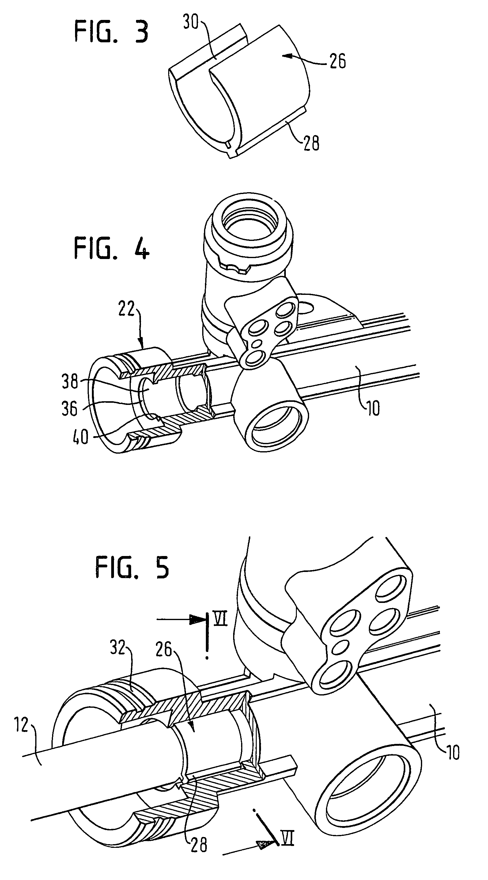
[0024]The area around the first end 22 of the housing 10 is shown in detail in FIG. 2. An auxiliary support 26 is provided between the ball joint 14 and the pinion 18 and limits a bending of the steering rack 12. The distance between the point of contact of the pinion 18 on th...


PUM


Abstract

A steering gear for a rack and pinion steering system, including a housing in which a steering rack is guided for displacement along its axis, has an auxiliary support which is located at an axial end of the housing, the auxiliary support limiting a bending of the steering rack.

Description

CROSS-REFERENCE TO RELATED APPLICATIONS[0001]This application is a National Stage of International Application No. PCT / EP2006 / 002781 filed Mar. 27, 2006, the disclosures of which are incorporated herein by reference in entirety, and which claimed priority to German Patent Application No. 20 2005 007 923.5 filed May 20, 2005, the disclosures of which are incorporated herein by reference in entirety.BACKGROUND OF THE INVENTION[0002]The invention relates to a steering gear for a rack and pinion steering system.[0003]Nowadays, rack and pinion steering gears are used almost exclusively in vehicle steering systems, in particular in cars. These steering gears comprise a steering rack which is guided for displacement in a housing along its axis, and a pinion which meshes with a serrated section of the steering rack and is connected to a steering wheel by means of a steering rod. The two axial ends of the steering rack project from the housing and are each joined to a tie rod by a ball joint...

Claims


Application Information

Patent Timeline
Patent Type & Authority Patents(United States)
IPC IPC(8): B62D3/12
CPCB62D3/12Y10T74/1967B62D3/00
Inventor SPAN, EDUARDBEISS, MARKUSKLEIN, THOMAS
Owner TRW AUTOMOTIVE GMBH
Why Eureka
Try Eureka