Vehicle seat

a technology for vehicles and seats, applied in vehicle seats, seating furniture, stools, etc., can solve the problems of inability to meet the requirements of suitable covers for back rest cushions, inconvenient manufacturing, and inconvenient use, and achieve the effect of satisfying the higher aesthetic requirements and being simple to manufactur

Inactive Publication Date: 2010-08-31
FALLEN MANFRED
View PDF28 Cites 96 Cited by
  • Summary
  • Abstract
  • Description
  • Claims
  • Application Information

AI Technical Summary

Benefits of technology

[0008]The object of the present invention is to provide a vehicle seat of the type mentioned at the beginning which allows circulation in the head, neck and shoulder area of the vehicle passenger and that satisfies the higher aesthetic requirements while being simple to manufacture.
[0010]The diverting surface of the diverting mechanism provided for this is preferably formed by an injection moulding part, particularly preferably in the form of a plastic shell, which is attached to the head cushion, namely preferably by mechanism of being clipped into place. This development allows the diverting surface to be shaped for the best possible diversion of the warm airflow to the neck and / or head area of the vehicle passenger. Concave and / or convex developments are consequently possible. In the case of a relatively bundled warm airflow flowing out of the upper area of the back rest, this warm airflow can be diverted and emitted in a comparatively diffuse manner in the direction of the head and / or neck area by means of the diverting mechanism. For this purpose, the diverting mechanism can particularly have a rough surface structure which breaks the relatively bundled warm airflow and softly diverts it to the neck and / or head area of the vehicle passenger.

Problems solved by technology

The aforementioned solution is relatively complex and furthermore unsightly, because it is not always possible to stretch the textile covering in such a way that there are no wrinkles.
This development requires uniform perforation of the upper area of the back rest, which leads to limitations with regard to the eligibility of suitable covers for the cushion of the back rest.
This development is also relatively complex.
Furthermore, the known solution does not allow for a neck flow that is adapted to the individual size of the vehicle passenger.
In conventional vehicle seats, in which the head restraint is arranged so as to be elevated above the back rest, such a development leads to an unsightly development with a pipe piece between the upper side of the back rest and the head restraint.
Furthermore, special measures, which make the design complex and expensive, must be taken in order to use pipes to form an airway that is airtight and that can be adjusted in the height.

Method used


Image

  • Vehicle seat
  • Vehicle seat
  • Vehicle seat

Examples


Embodiment Construction

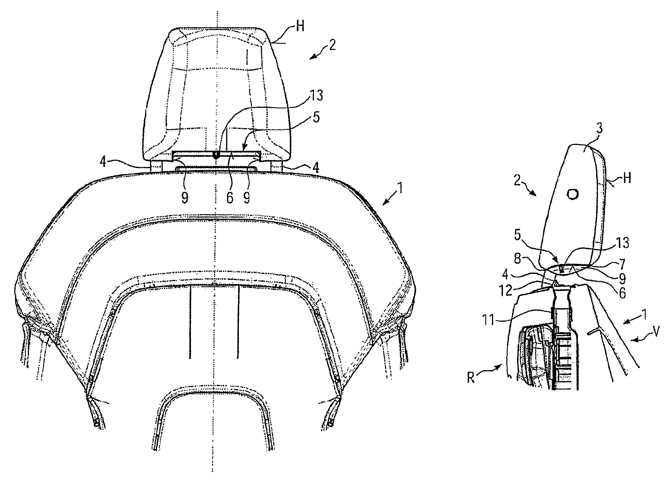
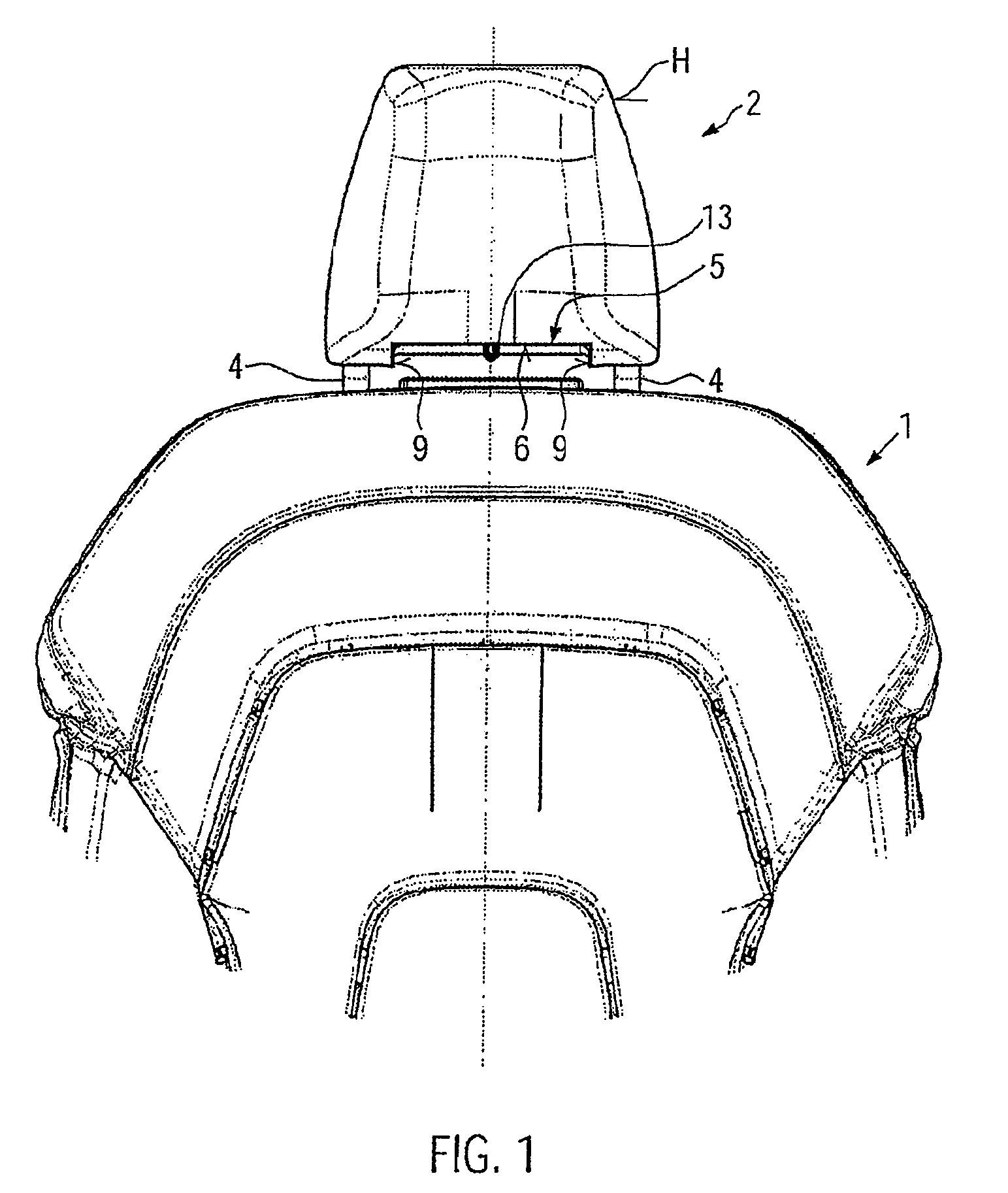
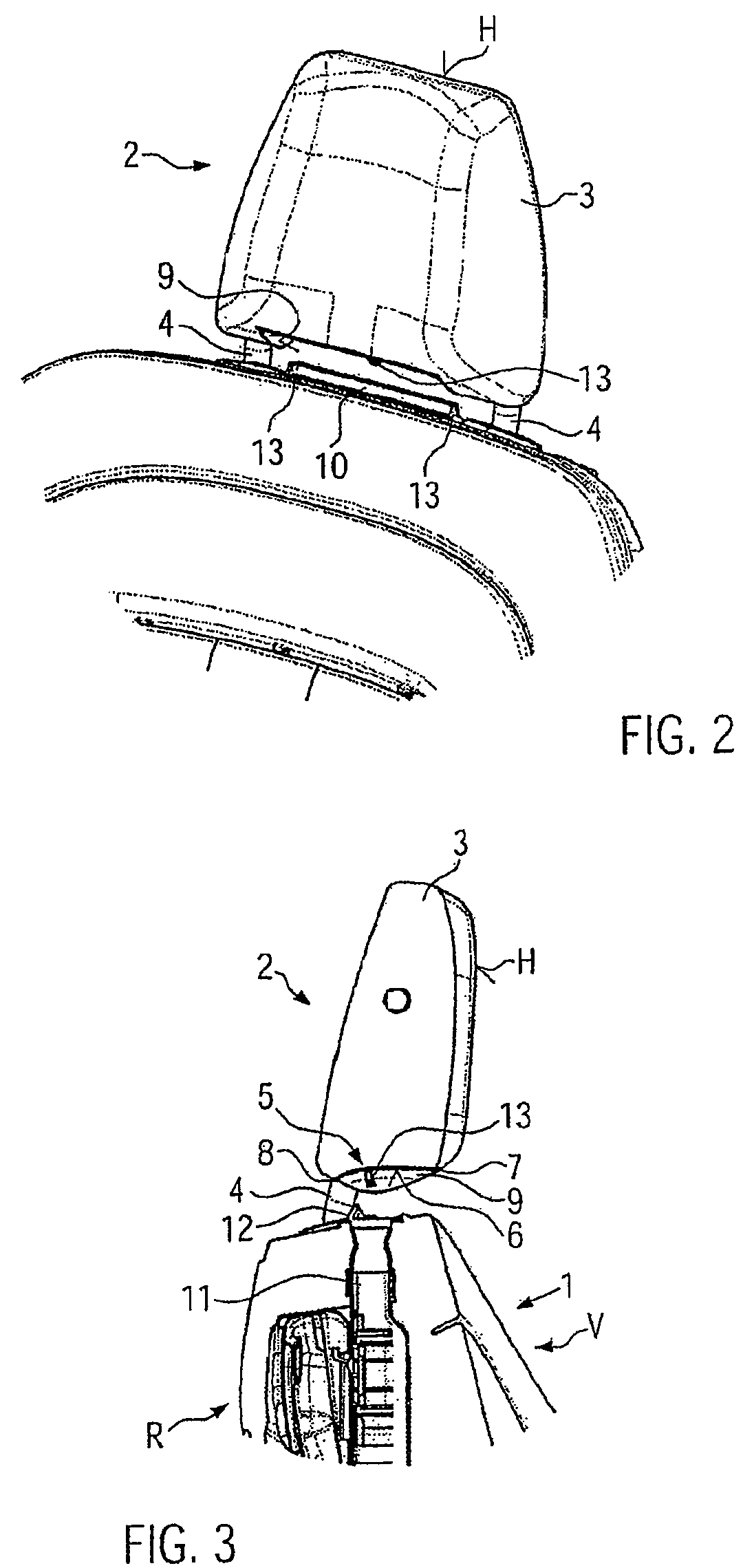
[0020]FIG. 1 shows the upper part of a back rest 1 of a vehicle seat, whose further parts are not of concern for the explanation of the invention. The back rest supports a head restraint 2 with a head cushion 3 that softly surrounds this head restraint. The head restraint 2 is mounted in such a way that its height can be adjusted relative to the back rest 1 via supporting bars 4, whereby the supporting bars 4 are held in a holder in the back rest 1 in a known way that allows them to be displaced.

[0021]On the part of the head restraint 2, between the supporting bars 4, is a diverting mechanism 5 which, in the case of the embodiment shown, is formed by an injection moulded plastic shell, whereby the outward pointing area of this forms a diverting surface 6 which is formed so that it is essentially concave and offset inward relative to a covering surface that surrounds the head cushion 3, so that it is provided integrated into the head cushion. This arrangement is particularly clear in...


PUM


Abstract

A vehicle seat has a back rest, a head restraint, which is adjustable in the height and which has a head cushion, and a ventilation device, whose exhaust vent for blowing out a warm airflow is arranged on the upper side of the back rest. The vehicle seat that has a construction that is simplified and aesthetically pleasing and that is characterized in that a diverting mechanism is provided in a lower area of the head restraint and is integrated into the head cushion. The warm airflow issuing from the exhaust vent is diverted into the head and / or neck area of a seat passenger via this diverting mechanism.

Description

BACKGROUND OF THE INVENTION[0001]1. Field of the Invention[0002]The present invention relates to a vehicle seat with a back rest, a head restraint, which is adjustable in the height and which has a head cushion, and a ventilation device, whose exhaust vent for blowing out a warm airflow is arranged on the upper side of the back rest.[0003]2. Description of the Related Art[0004]Such a generic vehicle seat serves, particularly in the case of a convertible, the circulation in the neck area of a vehicle passenger, especially when the roof is open, in order to compensate for the draught. A generic vehicle seat is known, for example, from DE 10 2004 002 074 83. In this state of the art, a textile membrane extends between the upper side of the back rest and the head cushion, whereby this textile membrane covers the interspace provided in between and works as a diffuser, so that the warm airflow that issues from the back rest at the upper side of the back rest between the textile covering a...

Claims


Application Information

Patent Timeline
Patent Type & Authority Patents(United States)
IPC IPC(8): A47C7/74
CPCB60N2/4808B60N2/4876B60N2/5621B60N2/58B60N2/5671B60N2/809B60N2/879
Inventor FALLEN, MANFRED
Owner FALLEN MANFRED
Why Eureka
Try Eureka