Mortar mixing apparatus

Active Publication Date: 2010-08-31
CUMMER THOMAS J
View PDF35 Cites 32 Cited by
  • Summary
  • Abstract
  • Description
  • Claims
  • Application Information

AI Technical Summary

Benefits of technology

[0009]It is a primary object of the invention to provide a mortar mixer which can discharge mortar without tipping of the mixer container. Another object of the invention is to provide a mortar mixer with an underlying discharge screw conveyor which can be operated in reverse to force materials within the screw conveyor housing upward into the container to be mixed thoroughly with other materials present in the container. It is a further object

Problems solved by technology

The mixing of the mortar in a first machine followed by its transfer to a hopper for transport creates i

Method used


Image

  • Mortar mixing apparatus
  • Mortar mixing apparatus
  • Mortar mixing apparatus

Examples


Embodiment Construction

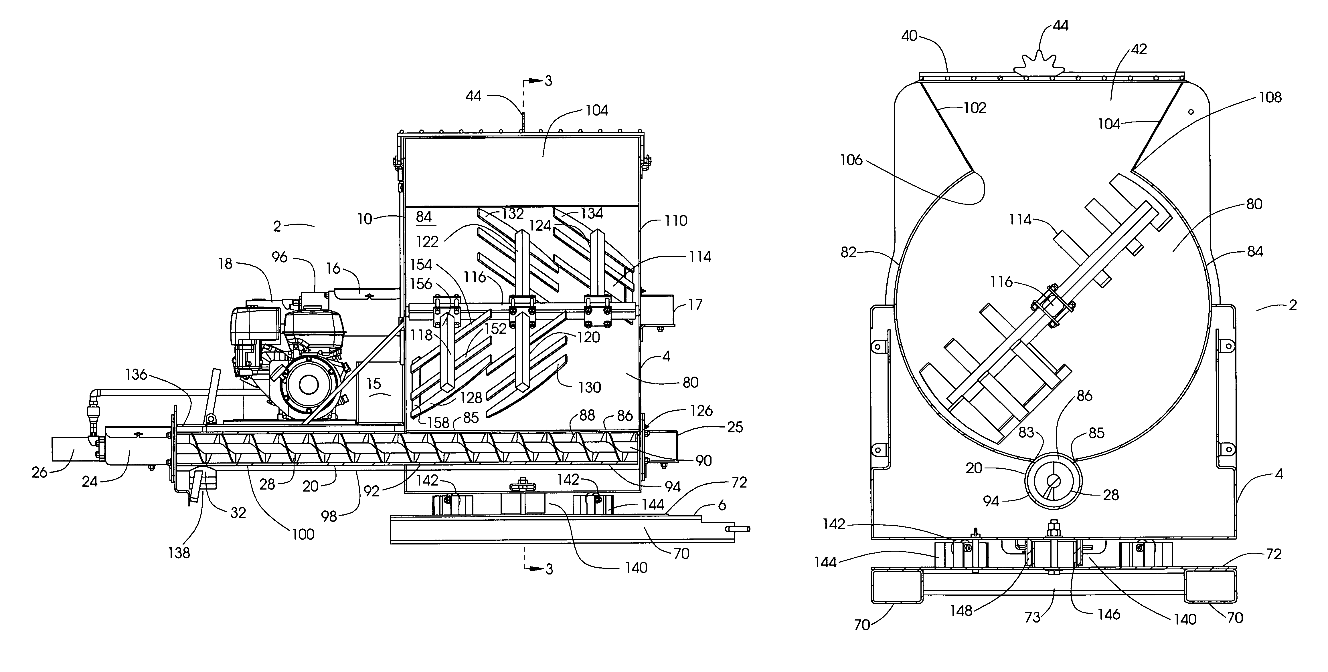
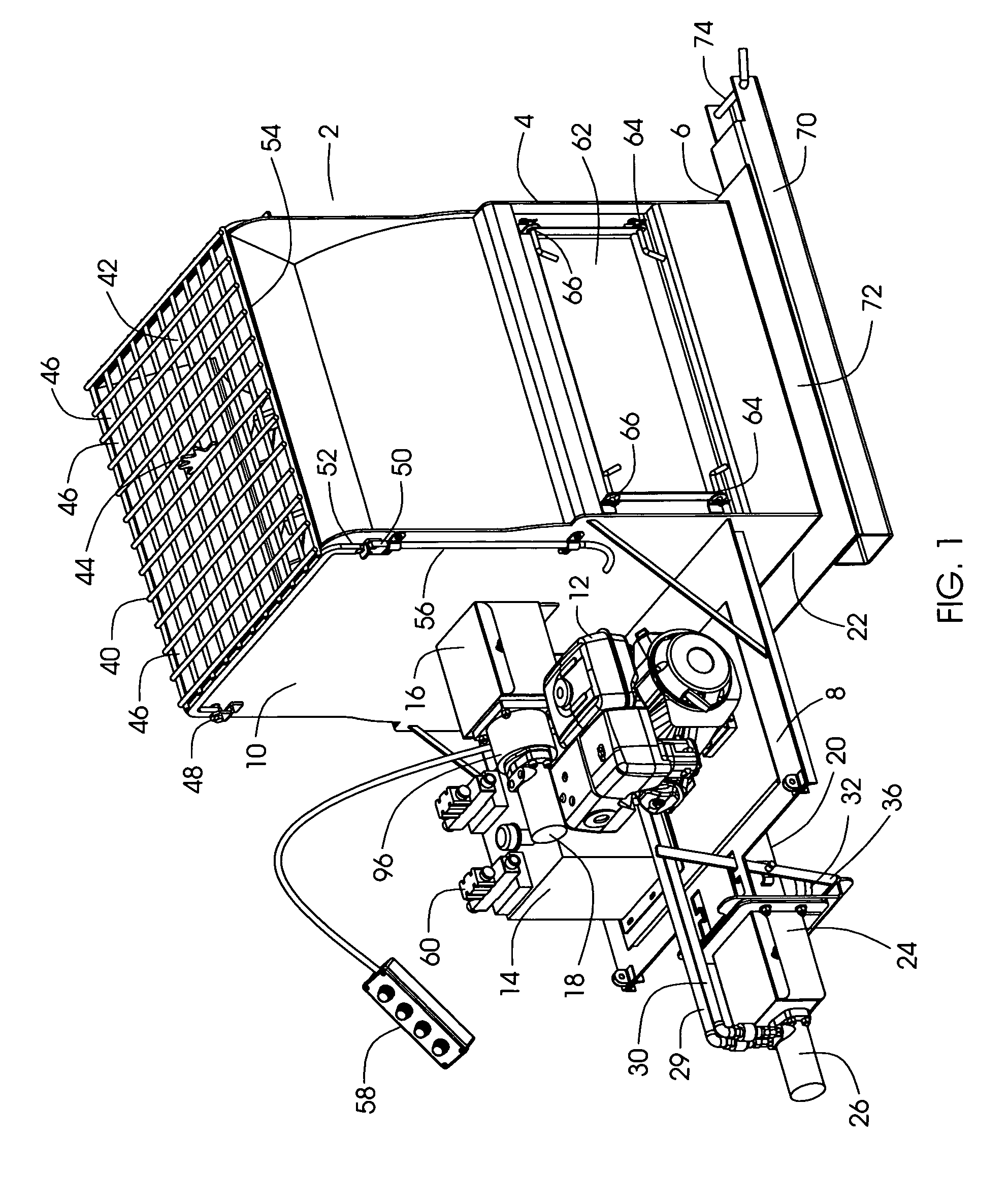
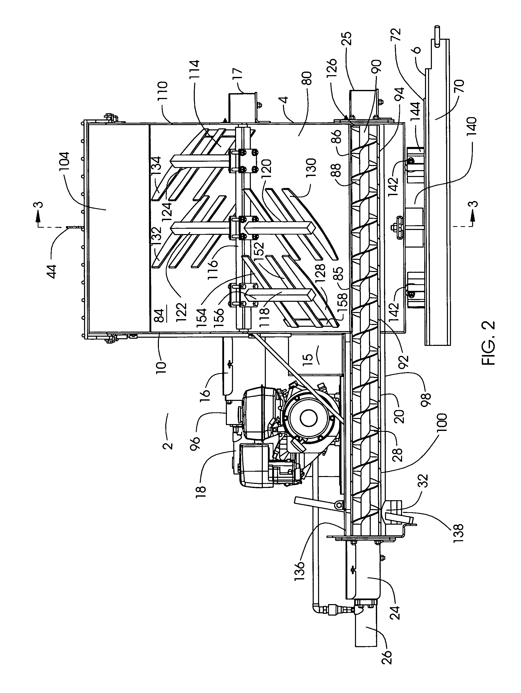
[0015]Referring to the drawings and particularly to FIG. 1, the mortar mixer invention 2 is shown ready for operation. Invention 2 comprises a housing 4 rotatably supported upon base 6. A shelf 8 supported on first end wall 10 of housing 4 supports an internal combustion engine 12 operatively coupled to a hydraulic pumping system 14. A battery may be supported on invention 2, preferably on shelf 8, to provide electrical power for control use and to power an optional starter for engine 12. Extending from first end wall 10 of housing 4 is first shaft coupler housing 16 from which gear box 96 and agitator drive motor 18 axially extend. Agitator drive motor 18 is operatively coupled to the hydraulic pumping system 14 so that agitator drive motor 18 may be selectively operated by pressurized hydraulic fluid supplied by a hydraulic pumping system 14. First shaft coupler housing 16 encloses conventional shaft coupling and shaft seal components.

[0016]Preferably screw conveyor 20 extends fro...


PUM

PropertyMeasurementUnit
Lengthaaaaaaaaaa
Forceaaaaaaaaaa
Flow rateaaaaaaaaaa

Abstract

A mortar mixing apparatus includes a screw conveyor disposed below the bottom of a mixing container in which a selectively operable agitator is located. An elongate opening in the bottom of the mixing container is open into the housing of the screw conveyor so that mixed mortar may flow into the screw conveyor. The screw conveyor may be rotated in a reverse direction to force materials upward into the mixing container, or it may be operated in a forward direction to convey mortar away from the mixing container. The agitator and the screw conveyor are independently driven by hydraulic motors.

Description

FIELD OF THE INVENTION[0001]This invention pertains to devices to mix mortar and other fluent materials used in masonry construction.BACKGROUND OF THE INVENTION[0002]In the conventional preparation of mortar for masonry applications, aggregate materials are mixed with lime, Portland cement and water in a mixer having an open-topped tub supported on an axle so that the tub can be tipped and its contents dumped into a transporting container which then can be moved closer to the site where the mortar is needed. The mixing tub of the conventional mortar mixer is provided with an agitator to cause intermixing of the ingredients of the mortar. When mortar is sufficiently well mixed by the agitator, the agitation is stopped so that the tub can be tipped by rotating it about its support so that the mortar contents will empty by gravity into a transporting container. An example of a conventional mortar mixer which can be tilted for dumping is found in Stone, deceased, U.S. Pat. No. 4,043,540...

Claims


Application Information

Patent Timeline
IPC IPC(8): B28C5/14
CPCB28C7/064B28C7/167B28C5/0893B28C5/1223B28C5/148B01F7/00133B01F7/00158B01F7/04B01F15/00545B01F15/027B01F15/0289B01F27/0723B01F27/0726B01F27/70B01F35/32045B01F35/752B01F35/754551
Inventor CUMMER, THOMAS J.
Owner CUMMER THOMAS J
Why Eureka
Try Eureka