
Tissue treatment system

a technology of tissue treatment and treatment system, applied in the field of tissue treatment system, can solve problems such as errors or fault indication

Inactive Publication Date: 2010-08-31
ENERGIST
View PDF72 Cites 61 Cited by
  • Summary
  • Abstract
  • Description
  • Claims
  • Application Information

AI Technical Summary

Benefits of technology

"The patent text describes a system for delivering pulsed energy to a tissue surface for treatment purposes. The system includes a handheld treatment instrument with a gas conduit and a nozzle for creating a plasma jet. The plasma jet is formed by a combination of an electrode and a gas powered by a separate r.f. power generator. The system also includes a calibration device with a target element and a temperature difference sensor to adjust the energy output of the generator. The calibration device is connected to the generator and the instrument to ensure consistent and accurate treatment. The technical effect of the invention is to provide an improved means of controlling treatment energy by calibrating the energy output with a reference value and adjusting it in response to any deviation in the calibration value. This ensures the delivery of the desired energy at the point of application and takes into account the variations in the components and processes involved."

Problems solved by technology

In an open-loop control system, deviation of one or more electrical parameters associated with the generator output from respective expected values by more than a certain degree may result in an error or fault indication, or in halt of the treatment by a control system forming part of the generator.

Method used


Image

  • Tissue treatment system
  • Tissue treatment system
  • Tissue treatment system

Examples


Embodiment Construction

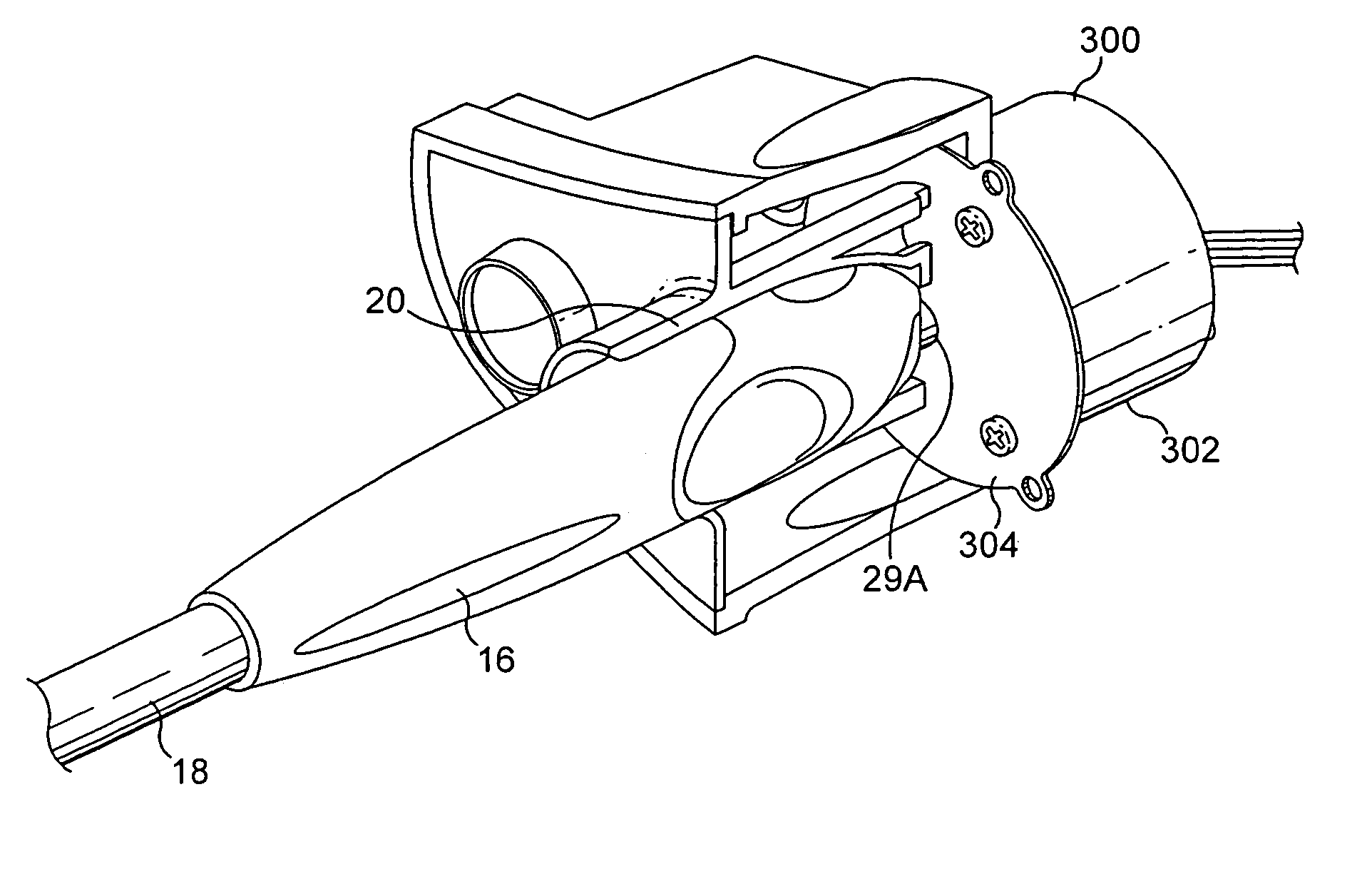
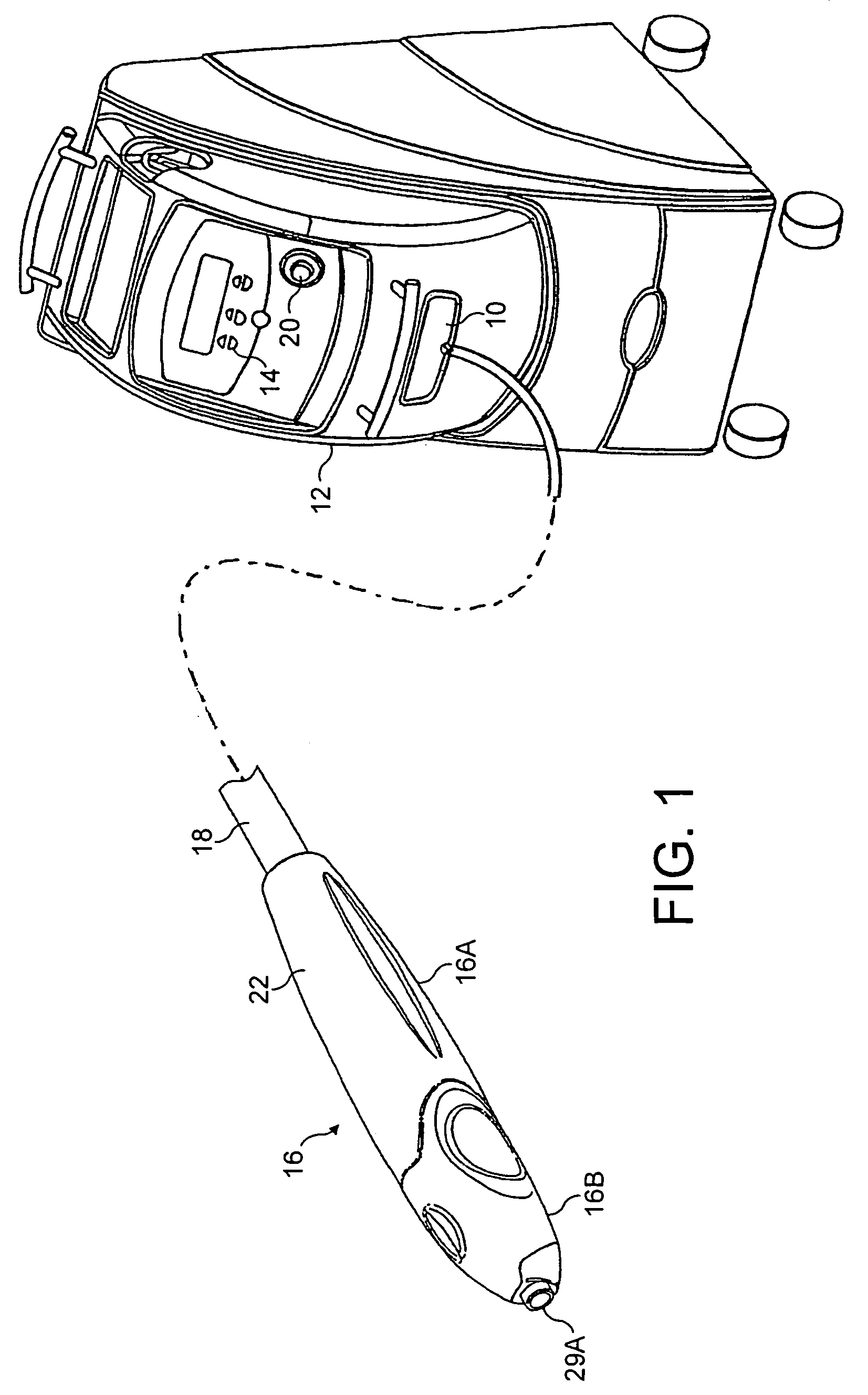
[0055]Referring to FIG. 1, a tissue treatment system in accordance with the invention has a generator 10 mounted in a floor-standing generator housing 12 and having a user interface 14 for setting the generator to different energy level settings. A handheld tissue treatment instrument 16 is connected to the generator by means of a cord 18. The instrument 16 comprises a re-usable handpiece part 16A and a disposable nose assembly 16B.

[0056]The generator housing 12 has an instrument holder 20 for storing the instrument when not in use.

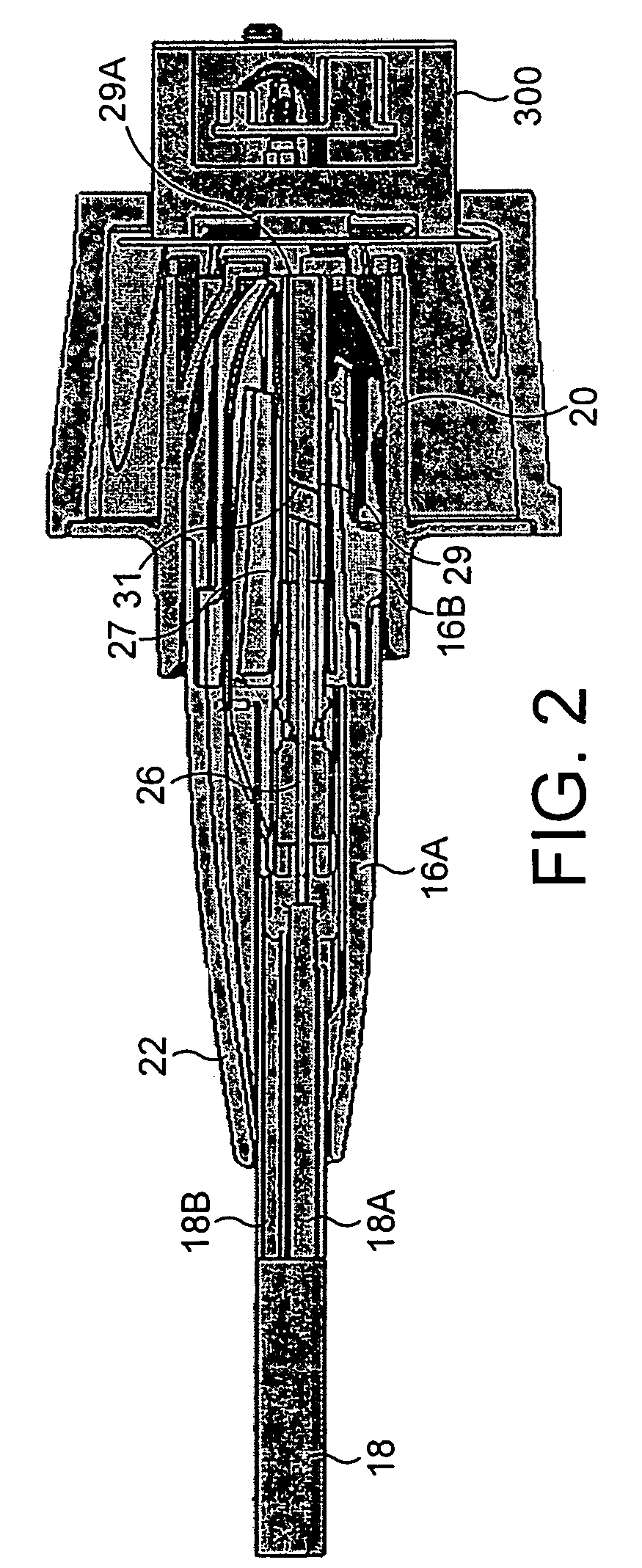
[0057]The cord 18 includes a coaxial cable for conveying r.f. energy from the generator 10 to the instrument 16, and a gas supply pipe for supplying nitrogen gas from a gas reservoir or source (not shown) inside the generator housing 12. At its distal end, the cord 18 passes into the casing 22 of the re-usable handpiece part 16A

[0058]In the re-usable handpiece 16A, the coaxial cable 18A is connected to inner and outer electrodes 26 and 27, as shown in FIG...


PUM


Abstract

A tissue treatment system has a radio frequency generator and a handheld treatment instrument that generates a gas plasma jet for delivering thermal energy to a tissue surface to be treated. Incorporated in the housing for the generator is a calibration device for adjusting the energy output of the generator, if necessary, at the beginning of a treatment session. The calibration device has a target element with a target surface, a transducer for sensing changes in temperature of the target element with respect to the temperature of a reference element, and an energy output adjuster for adjusting the radio frequency energy output of the generator in response to a calibration signal generated by the transducer. The generator housing has a receptacle for locating the nozzle of the handheld instrument in juxtaposition with the target element so that when a plasma burst is generated as part of a calibration sequence it is incident on the target surface. The generator output is automatically adjusted to compensate for any deviation of a calibration value, produced from the calibration signal, from a reference value. Also disclosed is a method of regenerating the reticular architecture of tissue, the method including calibrating the energy delivery of a tissue treatment system.

Description

[0001]This application claims priority of U.S. Provisional Patent Application No. 60 / 653,480, filed Feb. 17, 2005. This application is a Continuation-in-Part of U.S. patent application Ser. No. 10 / 792,765, filed Mar. 5, 2004 that is a Continuation-in-Part Application of U.S. patent application Ser. No. 09 / 789,550, filed Feb. 22, 2001, that in turn claims the benefit of priority of U.S. Provisional Patent Application No. 60 / 183,785, filed Feb. 22, 2000. The complete disclosures of U.S. Provisional Patent Application No. 60 / 653,480, U.S. patent application Ser. No. 10 / 792,765, U.S. patent application Ser. No. 09 / 789,550, and U.S. Provisional Patent Application No. 60 / 183,785, including the specification, drawings, and claims are incorporated herein by reference in their entirety.BACKGROUND OF THE INVENTIONField of the Invention[0002]This invention relates to a tissue treatment system including a radio frequency (r.f.) generator and a treatment instrument connectible to the generator a...

Claims


Application Information

Patent Timeline
Patent Type & Authority Patents(United States)
IPC IPC(8): A61B18/18
CPCA61B18/042A61B2017/00725
Inventor PENNY, KEITHGOBLE, NIGEL MARKGOBLE, COLIN CHARLES OWEN
Owner ENERGIST
Learn More