
Interactive depth of field using simulated heat diffusion

a technology of depth of field and simulation, applied in the field of computer graphics, can solve the problems of high cost of creating and direct effects, inability to accurately compute the depth of field effect in computer graphics rendering, and inability to accurately compute the depth of field effect. the effect is both costly and difficult to direct, and the computation needed to compute the effect is traditionally very slow and unwieldy

Inactive Publication Date: 2010-08-31
PIXAR ANIMATION
View PDF9 Cites 21 Cited by
  • Summary
  • Abstract
  • Description
  • Claims
  • Application Information

AI Technical Summary

Benefits of technology

"The present invention relates to methods and apparatus for creating interactive depth of field effects using simulated heat diffusion. The technical effects of this invention include the ability to create visually appealing and realistic depth of field effects in computer graphics, which can enhance the overall quality of computer-implemented games and other computer-based applications. The invention involves receiving information specifying an input image, determining a set of parameters associated with a pinhole camera, and blurring portions of the image using heat diffusion in a medium to create a first output image with a first depth-of-field effect. The invention also allows for the creation of a second output image with a second depth-of-field effect by matting different portions of the image and blurring them using heat diffusion in the medium. The invention can be implemented using a computer system with a CPU and a GPU, and a computer program product is also provided for this purpose."

Problems solved by technology

Unfortunately, the computations needed to compute these effects have traditionally been very slow and unwieldy.
As a consequence, the effects are both costly to create and difficult to direct.
Accordingly, accurate computation of depth-of-field effects in computer graphics rendering is generally very time consuming, creating a problematic workflow for film authoring.
The computation is particularly challenging because it depends on large-scale spatially-varying filtering that must accurately respect complex boundaries.
A variety of real-time DOF solutions have been proposed for games, but the compromises in quality required to achieve the necessary frame rates have made these attempts unsuitable for film.
Unfortunately, the accumulation buffer method requires a large collection of renderings to achieve a pleasing result, and the enormous geometric complexity of film-quality scenes makes this prohibitive.
Distributing energy properly in the face of occlusions is also a difficult task.
Though scatter techniques are commonly used in non-real-time post-processing packages, they are not the techniques of choice for today's real-time applications, primarily because of the cost of the sort, the lack of high-precision blending on graphics hardware, and the difficulty of conserving total image energy.
Nonetheless, the gather operation is still not very well matched to today's Single Instruction, Multiple Data (SIMD) graphics hardware, because of the non-uniformity of the sizes of circles of confusion.
The gathering method also has difficulty with edge discontinuities and edge bleed.
Moreover, even if efficiently implemented on target hardware, standard gather and scatter techniques have poor asymptotic complexity because the amount of work they do is the product of the number of pixels in the image and the average area of the circle of confusion.
For example, For an n×n image, standard gather and scatter algorithms are O(n4), which is clearly problematic for high-resolution film-quality images.
While down-sampling may provide a sensible compromise to achieve adequate performance for games on typical hardware, down-sampling causes artifacts that are unacceptable for film authoring, especially film preview.
Another problem with down-sampling is that existing techniques do not allow large-scale blurs to be computed efficiently in ways that respect the critical boundaries between in-focus objects and those that are out-of-focus.
As a result, the acceleration methods used to down-sample will cause unacceptable color bleeding.

Method used


Image

  • Interactive depth of field using simulated heat diffusion
  • Interactive depth of field using simulated heat diffusion
  • Interactive depth of field using simulated heat diffusion

Examples


Embodiment Construction

[0035]The present invention relates to computer graphics. More specifically, the present invention relates to methods and apparatus for creating interactive depth of field effects using simulated heat diffusion.

[0036]In various embodiments, methods and apparatus for generating depth-of-field (DOF) effects according to the present invention generate depth-of-field effects by simulating heat diffusion in a medium (e.g., a non-uniform or uniform medium) are provided. In general, simulating heat diffusion in the medium gives rise to separable spatially varying recursive filters that can compute large-kernel convolutions in constant time per pixel while respecting the boundaries between in-focus and out-of-focus objects.

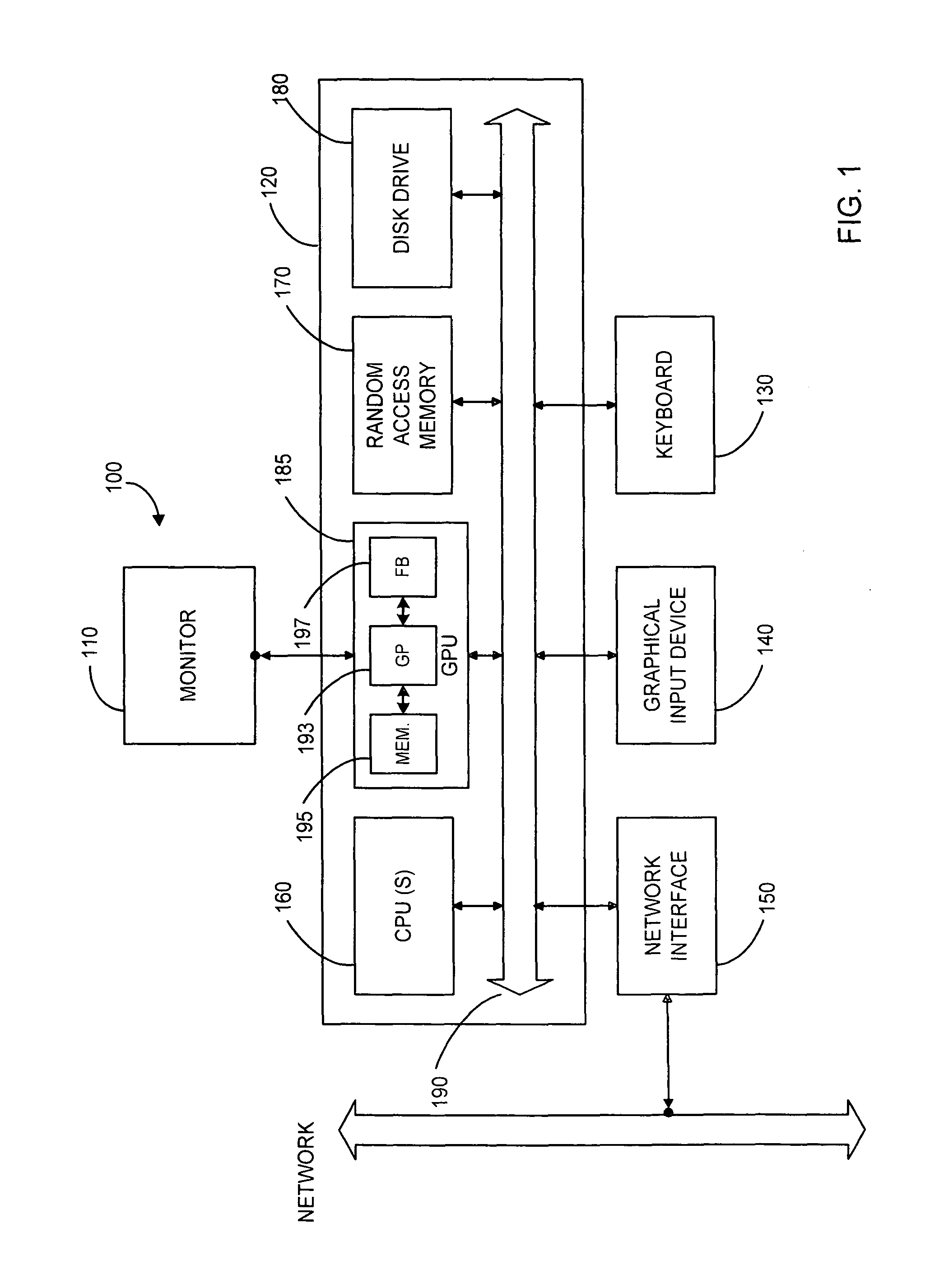
[0037]In some embodiments, methods and apparatus for generating depth-of-field (DOF) effects according to the present invention use a graphics processing unit (GPU). Depth-of-field effects may be vectorized and achieve interactive frame rates suitable for games and high-q...


PUM

PropertyMeasurementUnit
depth-of-field effectsaaaaaaaaaa
implicit solutionaaaaaaaaaa
heat equationaaaaaaaaaa

Abstract

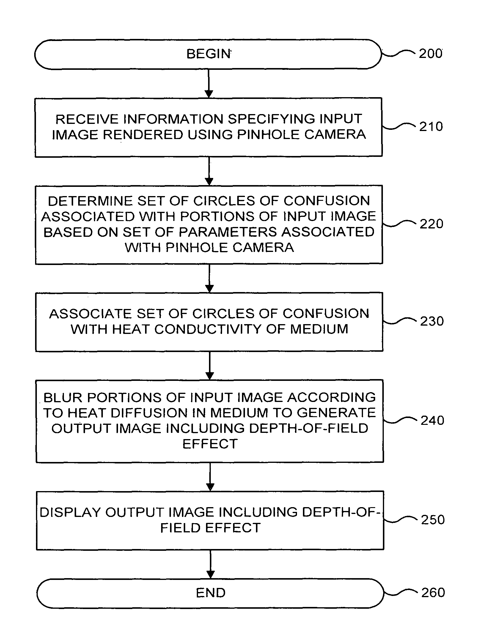
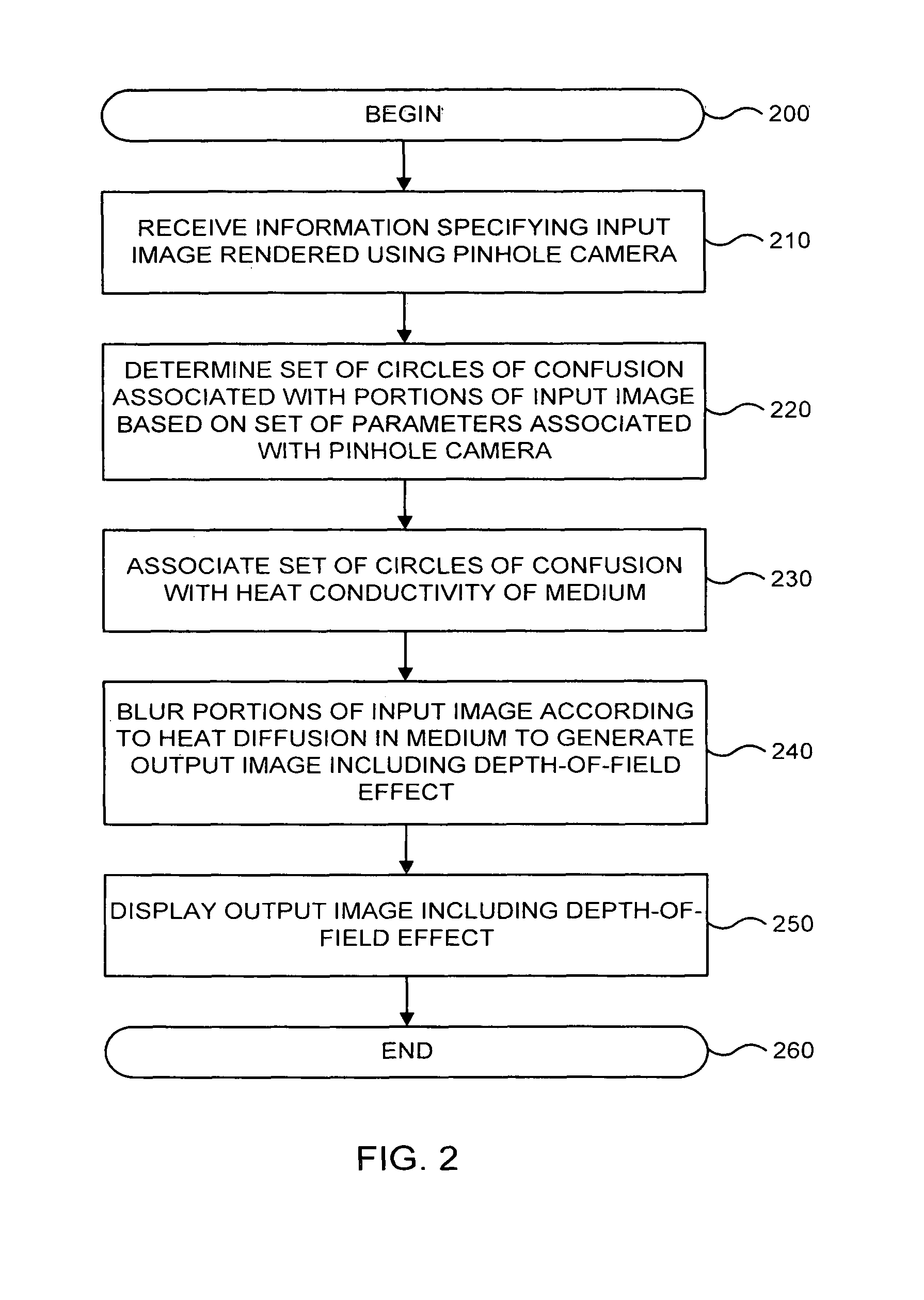
A computer-implemented method for generating depth-of-field effects includes receiving information specifying an input image rendered using a pinhole camera. A first set of circles of confusion associated with portions of the input image are determined based a set of parameters associated with the pinhole camera. The first set of circles of confusion are then associated with heat conductivity of a medium. The portions of the input image are blurred according to heat diffusion in the medium to generate a first output image having a first depth-of-field effect.

Description

CROSS-REFERENCES TO RELATED APPLICATIONS[0001]The present application claims the benefit of and priority to U.S. Provisional Application No. 60 / 762,237, filed Jan. 25, 2006, the disclosure of which is hereby incorporated by reference in its entirety for all purposes.BACKGROUND OF THE INVENTION[0002]The present invention relates to computer graphics. More specifically, the present invention relates to methods and apparatus for creating interactive depth of field effects using simulated heat diffusion.[0003]Depth-of-field (DOF) effects are essential in producing computer graphics imagery that achieves the look and feel of film. Unfortunately, the computations needed to compute these effects have traditionally been very slow and unwieldy. As a consequence, the effects are both costly to create and difficult to direct. Accordingly, accurate computation of depth-of-field effects in computer graphics rendering is generally very time consuming, creating a problematic workflow for film auth...

Claims


Application Information

Patent Timeline
Patent Type & Authority Patents(United States)
IPC IPC(8): G06K9/00G06K9/40G03C8/00G03C5/04G06G7/56G06G7/48H04N5/217
CPCG06T15/00
Inventor KASS, MICHAEL
Owner PIXAR ANIMATION
Learn More