Eye safety in electro-optical transceivers

a transceiver and electrooptical technology, applied in electromagnetic transceivers, transmission monitoring/testing/fault measurement systems, transmission monitoring, etc., can solve problems such as exacerbated problems, no accessible optical interface, and difficulty in meeting eye safety standards

Active Publication Date: 2010-08-31
SUMITOMO ELECTRIC DEVICE INNOVATIONS U S A
View PDF6 Cites 23 Cited by
  • Summary
  • Abstract
  • Description
  • Claims
  • Application Information

AI Technical Summary

Benefits of technology

[0011]Preferably, the signaling mode optical signal is an eye safe optical signal. More preferably the transmitted optical signal is a beacon signal of a predetermined format. Even more preferably the predetermined format is that the signal is on for a predetermined, relatively short and known, period of time, and then off for a predetermined, relatively long and known, period of time. The lower duty cycle of the optical signal will ensure that the average power level, if exposed, is safe.
[0012]In a preferred embodiment, the optical receiver lane signal detection circuitry is further arranged to detect the transmitted signaling mode optical signal, and the optical transmit lane control circuitry is further arranged to control a corresponding optical transmit lane to the receive lane on which the optical signal was received, to render any optical signals transmitted on the corresponding transmit lane eye safe.

Problems solved by technology

In the case of parallel optical transceivers, meeting the “eyesafe” standards can be difficult, because of the parallel nature of the arrangement.
The problem is exacerbated for integrated cable / transceivers, where the parallel ribbon fiber is permanently attached to the electro-optical transceivers at each end.
In this case, there is no accessible optical interface normally, and the optical power launched into the fibers is impossible to measure.
Moreover, since the optical interface is not accessible, there is an unknown coupling loss in assembly, and hence it is not desirable to limit the maximum permitted power from each of the VCSELs.
Thus, individual VCSEL optical emission may, in some cases, exceed the eye safety limit if exposed.
In addition the power launched into a single fiber might exceed safe level if exposed due to fiber breakage.
However, this means that a fault in a single one of the optical fibers results in the entire link being lost.

Method used


Image

  • Eye safety in electro-optical transceivers
  • Eye safety in electro-optical transceivers
  • Eye safety in electro-optical transceivers

Examples


Embodiment Construction

[0020]An embodiment of the invention will now be described.

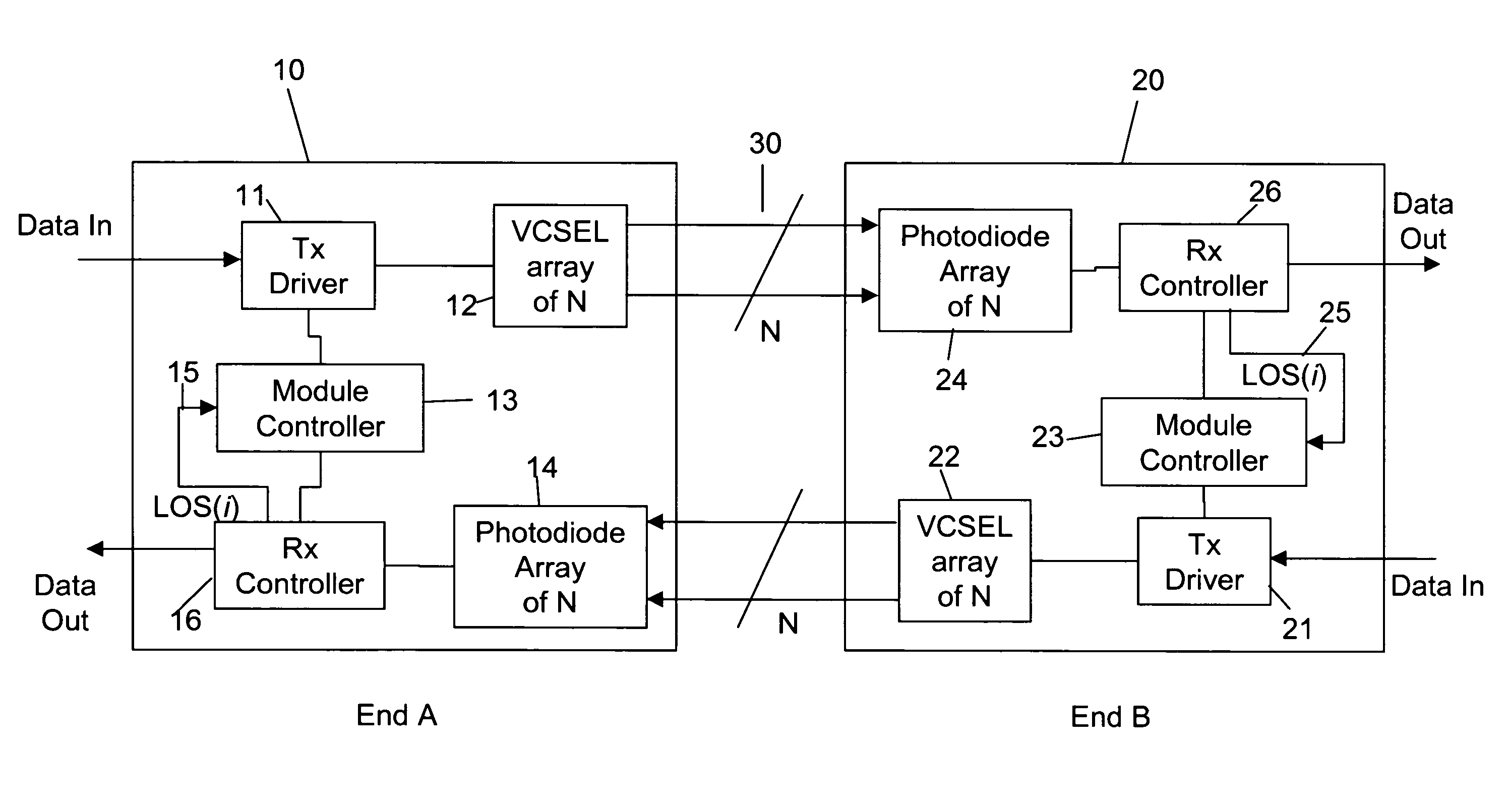
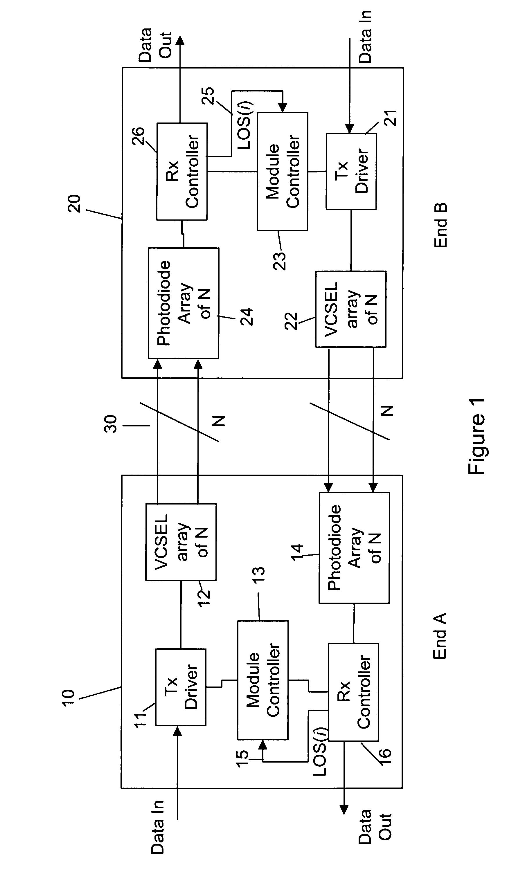
[0021]FIG. 1 is a block diagram illustrating two electro-optical modules according to an embodiment of the invention. A first electro-optical module 10 at end A is connected, via a parallel optical ribbon 30, to a second electro-optical module 20 at end B. The first electro-optical module 10 comprises a VCSEL array 12 comprising N VCSELs arranged in parallel. Also provided is a photodiode array 14, comprising N photodiodes arranged in parallel. A module controller 13 is further provided, as well as a receiver controller 16, arranged to receive signals from the photodiode array. A transmitter driver 11, which controls the VCSEL array is also included.

[0022]The transmitter driver 11 is arranged to receive data in, in the form of an electrical signal, and to control the VCSEL to convert the electrical signal into an optical signal, which is transmitted via the parallel optical fiber 30. Similarly, the parallel optical signal re...


PUM


Abstract

An electro-optical transceiver module having at least one parallel optical transmit lane and at least one parallel optical receiver lane, the module comprising optical receiver lane signal detection circuitry to detect a loss of signal on one or more of the receive lanes, and optical transmit lane control circuitry to control a optical transmit lane corresponding to the receive lane, on which a loss of signal was detected to transmit a signaling mode optical signal indicating the loss of signal on the receive lane. In a multiple lane parallel optic embodiment, and by signaling a loss of a signal on a per lane basis, a break or fault in a sub-set of fibers of a parallel optical link will not result in the entire parallel optic link being lost.

Description

BACKGROUND OF THE INVENTION[0001]1. Field of the Invention[0002]The present invention relates to a multi-channel or parallel electro-optical module and method of operation thereof wherein a loss of signal can be detected at a receive end of a parallel optical link, and information relating thereto communicated to a transmit end.[0003]2. Description of the Related Art[0004]A typical parallel optical transceiver consists of a vertical cavity surface emitter laser (VCSEL) array, to provide N optical beams coupled to N parallel optical transmission channels or lanes, and a photodiode array, to provide N parallel optical receiver lanes. A parallel optical fiber ribbon connects the transmitter array of the first optical transceiver, with the photodiode receiver array of a second optical transceiver, and vice versa.[0005]Various standards bodies typically dictate that in the case of a fault condition where laser light could be exposed, an optical transceiver should enter an “eyesafe” mode,...

Claims


Application Information

Patent Timeline
Patent Type & Authority Patents(United States)
IPC IPC(8): H04B10/08
CPCH04B10/07955H04B10/0799H04B10/40
Inventor WANG, XIAOZHONG
Owner SUMITOMO ELECTRIC DEVICE INNOVATIONS U S A
Why Eureka
Try Eureka