Method and system for calibrating a tube scanner

a tube scanner and tube technology, applied in the field of scanner instruments, can solve problems such as excessive error in scans, and achieve the effect of introducing excessive errors

Active Publication Date: 2010-08-31
KEY ENERGY SERVICES
View PDF44 Cites 8 Cited by
  • Summary
  • Abstract
  • Description
  • Claims
  • Application Information

AI Technical Summary

Benefits of technology

[0013]In yet another aspect of the present invention, the dependence of the results of a tube scan upon the speed at which the tube moves through the scanner is determined. The inventive tube scanner calibration may establish typical, fast limit, and slow limit metrics for the speed at which a tube should be moved through a tube scanner. The typical speed would be the one where the calibrated scanner reproduces expected scan values most closely and the fast limit and slow limit would be the scan speeds where the tube scanner still operates within tolerances, but movement of tubing through the tube scanner that is faster that the fast limit or slower than the slow limit may introduce excessive error into the scan. These limit values can be used by the crew to guide their operation of the rig while extracting or inserting tubing through the tube scanner.

Problems solved by technology

The typical speed would be the one where the calibrated scanner reproduces expected scan values most closely and the fast limit and slow limit would be the scan speeds where the tube scanner still operates within tolerances, but movement of tubing through the tube scanner that is faster that the fast limit or slower than the slow limit may introduce excessive error into the scan.

Method used


Image

  • Method and system for calibrating a tube scanner
  • Method and system for calibrating a tube scanner
  • Method and system for calibrating a tube scanner

Examples


Embodiment Construction

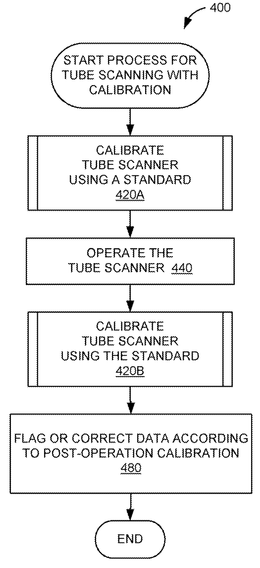
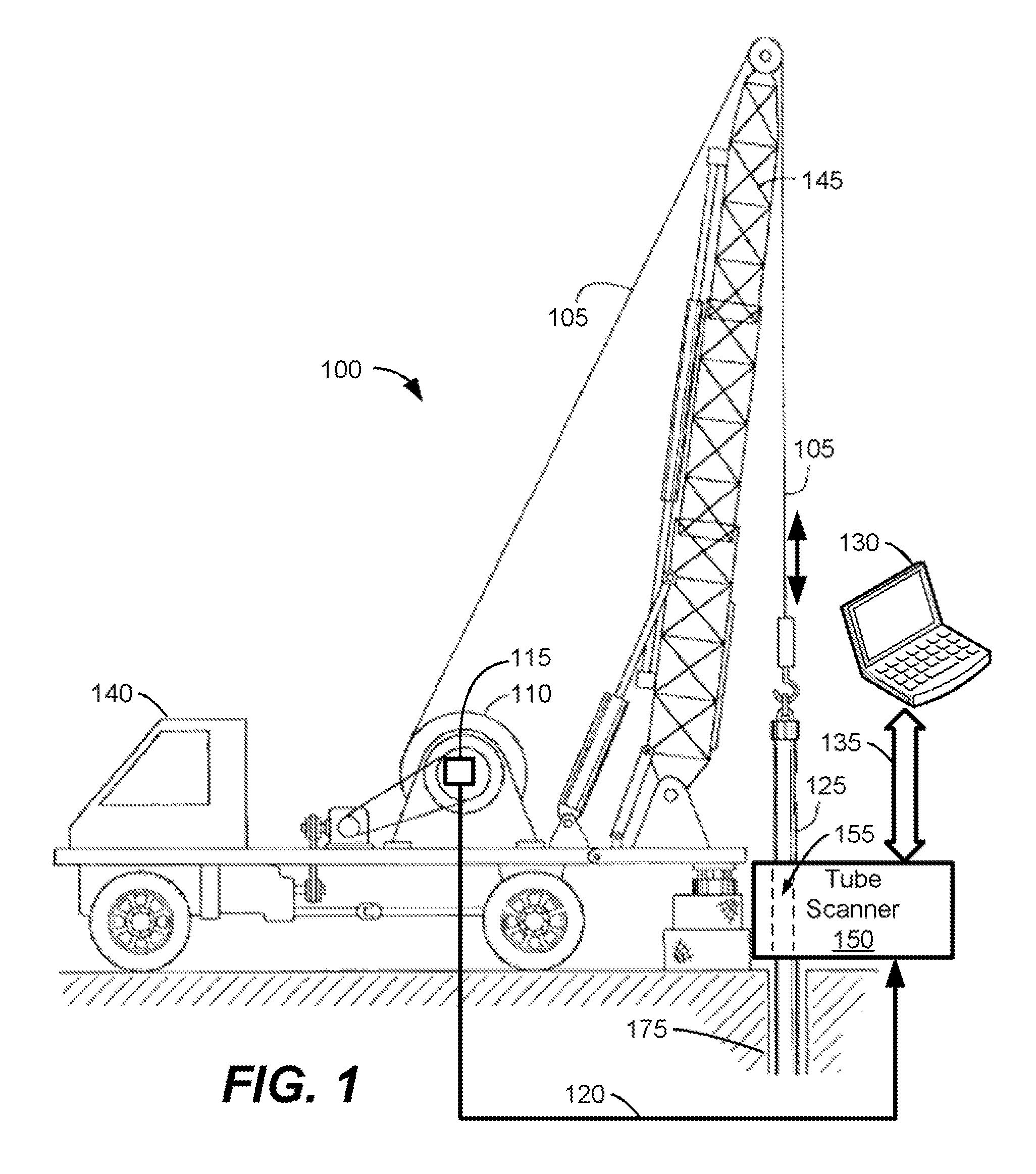
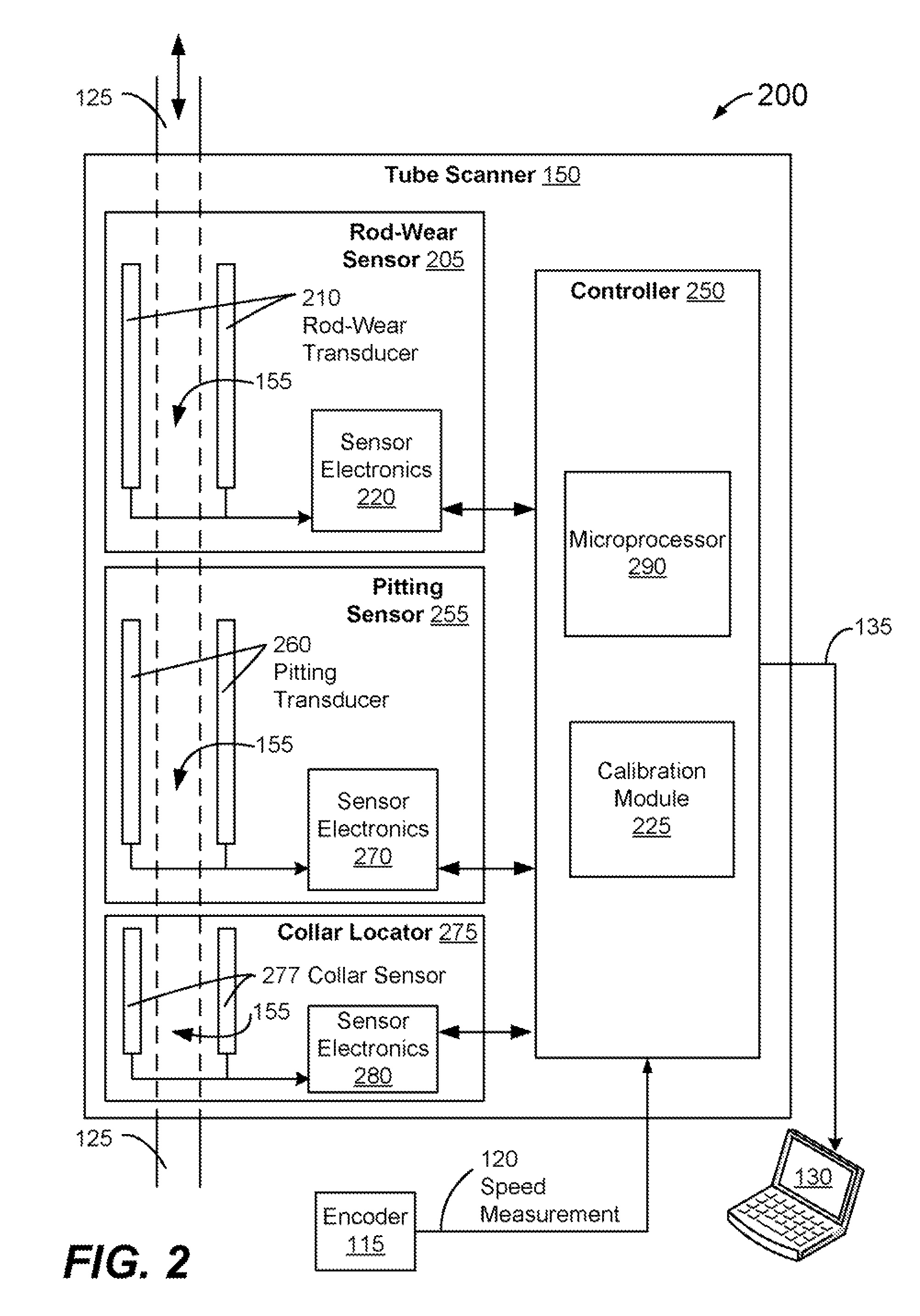
[0023]The present invention supports a method for calibrating a tube scanner used to scan tubing being placed into or being removed from a well. An exemplary method and system for calibrating the tube scanner will now be described more fully hereinafter with reference to FIGS. 1-6. These figures show representative embodiments of the present invention. FIG. 1 depicts a workover rig moving tubing through a tube scanner in a representative operating environment for one embodiment of the present invention. FIG. 2 provides a block diagram of a tube scanner that monitors, senses, or characterizes tubing and that validates and interprets tubing data. FIG. 3 depicts an exemplary tubing standard for calibrating the tube scanner illustrated in FIG. 2. FIGS. 4, 5 and 6 provide flow diagrams of methods for calibrating a tube scanning instrument.

[0024]The invention can be embodied in many different forms and should not be construed as limited to the embodiments set forth herein; rather, these e...


PUM


Abstract

A scanner instrument used for scanning tubing that is being placed into an oil well or being removed from the oil well can be calibrated during retrieval of tubing from the well. Calibrating the tube scanner includes scanning a tubing standard and comparing the data from the standard scan to the known characteristics of the standard. The relationship between the scanned data and the known characteristics can be computed. The relationship between the scanned data and the known characteristics can be used as the calibration function for the scanner. Calibrating the tube scanner can also include scanning a string of tubing segments and then adjusting the data collected. The adjustment is based upon equalizing the data peaks that occur in the scan data at the coupling joints between tube segments.

Description

[0001]This application claims benefit of U.S. Provisional Application Ser. No. 60 / 786,661, filed on Mar. 28, 2006.FIELD OF THE INVENTION[0002]The present invention relates generally to a scanner instrument for collecting and analyzing data describing a tube associated with an oil well and relates more specifically to calibration of the scanner instrument.BACKGROUND[0003]During the drilling, completion and maintenance of an oil well, personnel routinely insert and / or extract devices such as tubing, tubes, pipes, rods, hollow cylinders, casing, conduit, collars, and duct into the well. For example, a service crew may use a workover rig or service rig to extract a string of tubing and sucker rods from a well that has been producing petroleum. The crew may inspect the extracted tubing and evaluate whether one or more sections of that tubing should be replaced due to physical wear, thinning of the tubing wall, chemical attack, pitting, or other defect. The crew typically replaces section...

Claims


Application Information

Patent Timeline
Patent Type & Authority Patents(United States)
IPC IPC(8): G01B21/30G01M99/00
CPCE21B41/00G01N2291/02872G01B21/30
Inventor NEWMAN, FREDERIC M.
Owner KEY ENERGY SERVICES
Why Eureka
Try Eureka