Combined sight oil level gage and ultrasonic sensor

a technology of ultrasonic sensor and oil level, which is applied in the direction of positive displacement liquid engine, liquid fuel engine, instruments, etc., can solve the problems of not giving a correct indication of oil level, requiring a person to visually check the oil level, and no way to verify the level

Inactive Publication Date: 2010-09-07
GERBER LIONEL +1
View PDF22 Cites 14 Cited by
  • Summary
  • Abstract
  • Description
  • Claims
  • Application Information

AI Technical Summary

Benefits of technology

[0013]The present invention also provides for a new and unique pump having a bearing frame or housing with the combined fluid level sight gage and ultrasonic sensor arranged therein, as well as a new and unique pump controller that responds to such an ultrasonic sensor signal, for either controlling the operation of the pump, for providing either an audio or visual warning, or some combination thereof. The present invention also provides a new and unique pump system featuring such a combined fluid level sight gage and ultrasonic sensor in combination with such a pump controller.
[0014]Furthermore, the present invention also provides a new and unique method featuring steps of arranging a combined fluid level sight gage and ultrasonic sensor having a fluid level sight gage with a housing for containing a fluid and a sight glass for viewing the level of the fluid therein; sensing with an ultrasonic sensor coupled to the housing the level of fluid in the housing; and providing an ultrasonic sensor signal containing information about the level of fluid in the housing. The method may also feature steps for responding to the ultrasonic sensor signal; and either controlling the operation of the pump, or providing either an audio or visual warning, or some combination thereof.

Problems solved by technology

However, the disadvantage of the sight glass oil level is that it requires a person to visually check the oil level.
The disadvantage of the capacitive sensors is that it may or may not give a correct indication of oil level depending on the presence of contamination in the oil and the correct calibration and set-up of the sensor.
There is no way to verify that the level is correct.
Unfortunately, the difference between the dielectric constant of oil versus air is small.
If the oil is contaminated with even small amounts of water the dielectric properties are drastically altered making oil level measurements inaccurate or suspect at best.
If oil flows out, the level is too high.
However, the disadvantage of the level plug is that it requires a person to physically remove a plug with some type of tool and visually check for the presence of oil.
However, the disadvantage of using a dip stick to monitor oil level is that it requires a person to physically remove the stick, wipe off the oil, reinsert the stick, remove the stick and match the wetted oil line with the marking on the stick.
This also exposes the oil to contamination from the surroundings.

Method used


Image

  • Combined sight oil level gage and ultrasonic sensor
  • Combined sight oil level gage and ultrasonic sensor
  • Combined sight oil level gage and ultrasonic sensor

Examples


Embodiment Construction

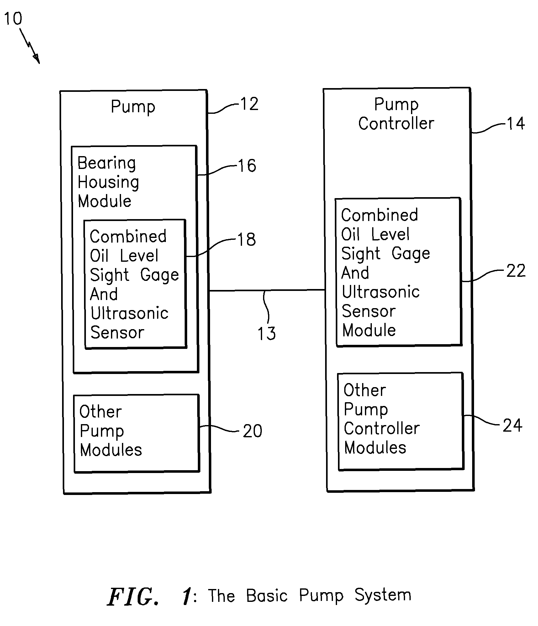
[0027]FIG. 1 shows, by way of example, a pumping system or other suitable rotating equipment generally indicated as 10, having a pump or other suitable rotating device 12 coupled to a pump controller 14 via a line 13 that provides data and control signals between the pump 12 and pump controller 14.

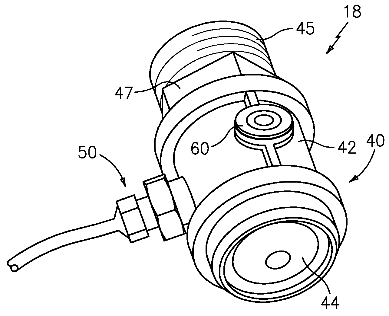
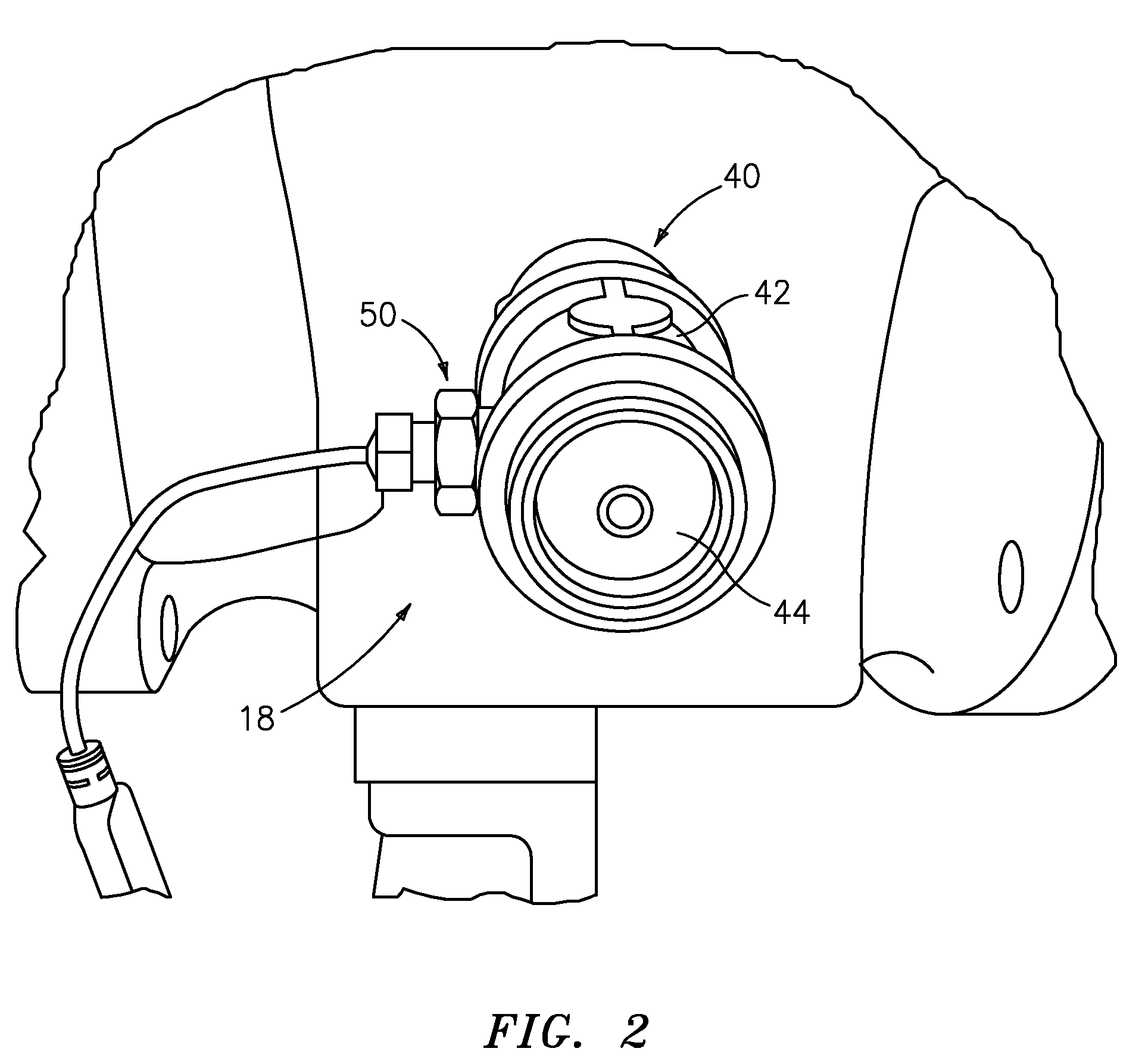
[0028]The pump 12 includes a bearing frame or housing 16 having a combined oil level sight gage and ultrasonic sensor 18 according to the present invention arranged therein. In operation, consistent with that shown and described herein, the combined oil level sight gage and ultrasonic sensor 18 has a fluid level sight gage 40 with a housing 42 for containing a fluid and having a sight glass 44 for viewing the level of the fluid therein, as best shown in FIGS. 2-3 and 5; and an ultrasonic sensor 50 coupled to the housing that responds to the level of fluid in the housing, for providing an ultrasonic sensor signal containing information about the level of fluid in the housing, as best shown ...


PUM


Abstract

The invention provides a combined fluid level sight gage and ultrasonic sensor featuring a fluid level sight gage having a housing for containing a fluid and having a sight glass for viewing the level of the fluid therein, and an ultrasonic sensor coupled to the housing, responsive to the level of fluid in the housing, for providing an ultrasonic sensor signal containing information about the level of fluid in the housing. In operation, the sight glass provides a visual verification that the ultrasonic sensor is working correctly in relation to the fluid visible in the sight glass. The ultrasonic sensor signal may be used to automatically annunciate alarms or warnings either locally at the equipment or by wired or wireless electronic means. In some embodiments according to the present invention, the housing has a centerline for indicating a normal fluid level therein. The ultrasonic sensor may be arranged in the housing on the centerline, or slightly below the centerline, or slightly above the centerline.

Description

CROSS-REFERENCE TO RELATED APPLICATION[0001]This application claims benefit to provisional patent application Ser. No. 60 / 881,809, filed 19 Jan. 2007, which is hereby incorporated by reference in its entirety.BACKGROUND OF THE INVENTION[0002]1. Technical Field[0003]The present invention generally relates to a sensor or gage; and more particularly to a sensor or gage for arranging in a bearing frame or housing of a pump forming part of a pumping system.[0004]2. Description of Related Problem There are several commonly employed methods for determining the fluid level, e.g. oil, in bearing frame housing of rotating equipment:[0005]For example, a sight glass oil level gauge may be screwed into the bearing housing in such a way that the center of the gage is located at the desired oil level. The gage uses a transparent glass or plastic window 6 to view the oil level. FIG. 8 shows, by way of example, one such known gage generally indicated as 5. The correct oil level is achieved when the ...

Claims


Application Information

Patent Timeline
Patent Type & Authority Patents(United States)
IPC IPC(8): G01F23/02G01F23/28
CPCF04B51/00F04B53/16G01F23/0069G01F23/02G01F23/296G01F23/802
Inventor QUILL, JEREMIAH D.
Owner GERBER LIONEL
Why Eureka
Try Eureka