Centrifugal impeller

a centrifugal impeller and centrifugal technology, applied in the direction of liquid fuel engines, vessel construction, marine propulsion, etc., can solve the problems of reducing the sound pressure affecting the efficiency of centrifugal impeller operation, etc., to achieve the effect of efficient distribution and reducing the noise level of discrete tones

Active Publication Date: 2010-09-07
IND TECH RES INST
View PDF12 Cites 10 Cited by
  • Summary
  • Abstract
  • Description
  • Claims
  • Application Information

AI Technical Summary

Benefits of technology

[0008]Regarding the drawbacks of the abovementioned conventional technologies, one of the objectives of this invention is to provide a centrifugal impeller, which can reduce the operating noise.
[0009]Another object of this invention is to provide a centrifugal impeller, which can reduce the sound pressure level of tones noise.
[0011]Still another object of this invention is to provide a centrifugal impeller, which can enhance the balance of rotation.
[0017]Consequently, the design of the present invention forms a periodically changed impeller structure whose blades have different angle intervals. The concentrated energy of the discrete tones noise generated by the rotating blades of the impeller can be efficiently distributed to the sideband frequency of the blades passing frequency and the other harmonic frequencies. The sound pressure level of the discrete tones noise is reduced. Thus the operating noise problem of the centrifugal machine is solved.

Problems solved by technology

However, for the operation of the centrifugal machine 1, the pressure variation of the working fluid flowing with high velocity and the blades rotated at high speed will resulted in considerable noises.
Generally, there is a considerably concentrated noise energy on the blade passing frequency of the impeller.
This is why the operation of conventional centrifugal impellers always has a very high noise level.
The noises caused by the centrifugal machine mainly comprise broadband noise and discrete tones noise.
The broadband noise is generated because of the pressure pulsation caused by the peeling off of the boundary layer of the turbulent flow.
However, it is difficult for the practical design to reduce the broadband noise by changing the hydrodynamics or aerodynamics design of the elements for achieving better design of flow field and machine efficiency.
Because the centrifugal machine needs to be driven and adjusted in a wide range, it is not easy to acquire the parameters of operation in a wide range and high efficiency.
That will be the key issue for the hydrodynamics or aerodynamics design.
However, this method can't meet the requirements of batch producing because of its disadvantages of complicated structure and high cost.
Although noise can be reduced in such designs, the impedance of the runner will thus increase, and the operating efficiency will thus degrade, which can not meet practical requirements either.
It is the key issue to design a type of centrifugal impeller for the conventional centrifugal machines not only to solve the operating noise problems but also to meet the requirement of design cost and flow impedance.

Method used


Image

  • Centrifugal impeller
  • Centrifugal impeller
  • Centrifugal impeller

Examples


first embodiment

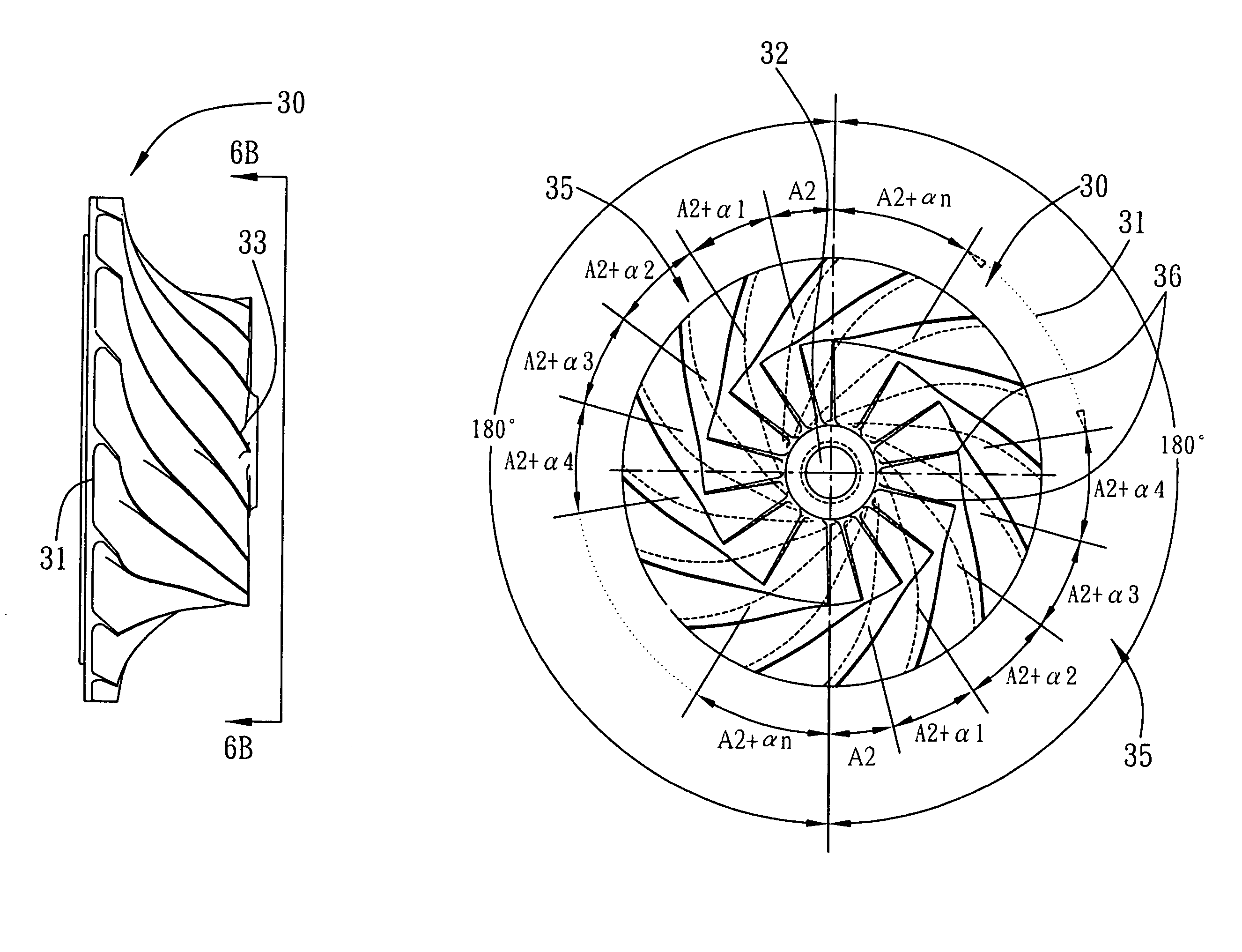
[0029]The centrifugal impeller 30 of the present invention is employed in the abovementioned conventional centrifugal machine, and has a structure shown in FIGS. 6A and 6B. The centrifugal impeller 30 comprises a conical impeller main body 31. A shaft bore 32 is installed in a center portion of the conical impeller main body 31 for a shaft 33 to pass. The shaft 33 is perpendicular to a plane where the conical impeller main body 31 is disposed on. The conical impeller main body 31 is evenly divided into a plurality of segments. In a first embodiment shown in the figures, the main body 31 is evenly divided into two segments. Two blade groups 35 are arranged surrounding the shaft 33 in sequence. Each of the two blade groups 35 comprises a plurality of blades 36 spaced at different angle intervals. The blades 36 have an interval angle which is a constant increment angle of α (the angle increase can also be designed to be different). The two blade groups 35 have the same number of blades...

second embodiment

[0033]According to the present invention, the main body 31 can be evenly divided into another number, in addition to two as described above, segments. In a second embodiment as shown in FIG. 8, the main body 31 is evenly divided into three segments, and three blade groups 35 are therefore formed. In the same scenario, neighboring blades 36 of each of the three blade groups 35 have an interval angle which is a constant increment angle of y, and the number and angle interval of the blades 36 of each of the blade groups 35 are identical. That is, the blades 36 of the three blade groups 35 are 120 degrees symmetrical to one another.

third embodiment

[0034]Alternatively, a third embodiment as shown in FIG. 9, the main body 31 is evenly divided into four segments, and four blade groups 35 are therefore formed. Neighboring blades 36 have an interval angle which is a constant increment angle of β, and the number and angle interval of the blades 36 of each of the blade groups 35 are identical. That is, the blades 36 of the four blade groups 35 are 90 degree symmetrical to one another.

[0035]Consequently, there is no limit to the number of the blade groups 35 of the present invention, the main body 31 can also be evenly divided into other number of segments and therefore the number of blade groups are formed, as long as a periodically changed impeller structure whose blades having different angle intervals is formed. Additionally, it is not necessary for the angle interval of neighboring blades 36 in a same blade group to have an increment angle of α, any other angle interval can also be adopted, as long as the corresponding angle int...


PUM


Abstract

A centrifugal impeller employed in a centrifugal machine, includes a main body, the main body generally being conical and defining a shaft bore in a center portion thereof; and a plurality of blade groups evenly arranged surrounding the shaft bore in sequence, each of the blade groups having a plurality of blades wherein neighboring blades having an interval angle, and the number and corresponding interval angles of the blades of different blade groups are identical. The present impeller structure can be employed to distribute the concentrated energy of the discrete tones noise of the blades, which is generated by the high-speed rotation impeller, and further to reduce the operating tones noise.

Description

FIELD OF THE INVENTION[0001]The present invention relates to a centrifugal impeller, especially to a low noise centrifugal impeller employed in centrifugal type of turbomachinery.BACKGROUND OF THE INVENTION[0002]Centrifugal type of turbomachinery, such as centrifugal compressors, centrifugal pumps or centrifugal fans, adopts a centrifugal machine to impel working fluid. In general, a centrifugal machine consists of two principal parts: an impeller(s), which forces the working fluid to flow into a rotary motion by impelling action, and a volute casing, which directs the working fluid to the impeller(s) and leads the working fluid away under a higher pressure. A general structure of a conventional centrifugal machine 1 is as shown in FIG. 1. The centrifugal machine 1 comprises a suction chamber 11, a centrifugal impeller 12, a diffuser 13, a volute casing 14 and an impeller shaft 15. In the operation thereof, a working fluid enters the centrifugal machine 1 via the suction chamber 11....

Claims


Application Information

Patent Timeline
Patent Type & Authority Patents(United States)
IPC IPC(8): F01D5/00
CPCF04D29/284F04D29/666
Inventor CHIANG, CHUNG-PINGCHEN, JIING FUCHOW, YUNG-LOYEN, CHENG-CHUNG
Owner IND TECH RES INST
Why Eureka
Try Eureka