Use of magneto-impedance on a contactless position sensor and corresponding sensor

a technology of contactless position sensor and magneto-impedance, which is applied in the direction of converting sensor output, magnitude/direction of magnetic field, measurement device, etc., can solve the problem of high cost imposed

Inactive Publication Date: 2010-09-07
CONTINENTAL AUTOMOTIVE FRANCE
View PDF6 Cites 11 Cited by
  • Summary
  • Abstract
  • Description
  • Claims
  • Application Information

AI Technical Summary

Benefits of technology

[0036]or this surface area is obtained by varying the density of the

Problems solved by technology

The problem posed here is that of how to widen the field of application of magnetoimpedance, on the basis of the abovementioned physical phenomenon, without necessarily having to measure very precisely the magne

Method used


Image

  • Use of magneto-impedance on a contactless position sensor and corresponding sensor
  • Use of magneto-impedance on a contactless position sensor and corresponding sensor
  • Use of magneto-impedance on a contactless position sensor and corresponding sensor

Examples


Embodiment Construction

[0060]The object of the approach here is therefore a priori not to make an exact quantitative measurement (a measurement of the external magnetic field as was the case with GMI sensors).

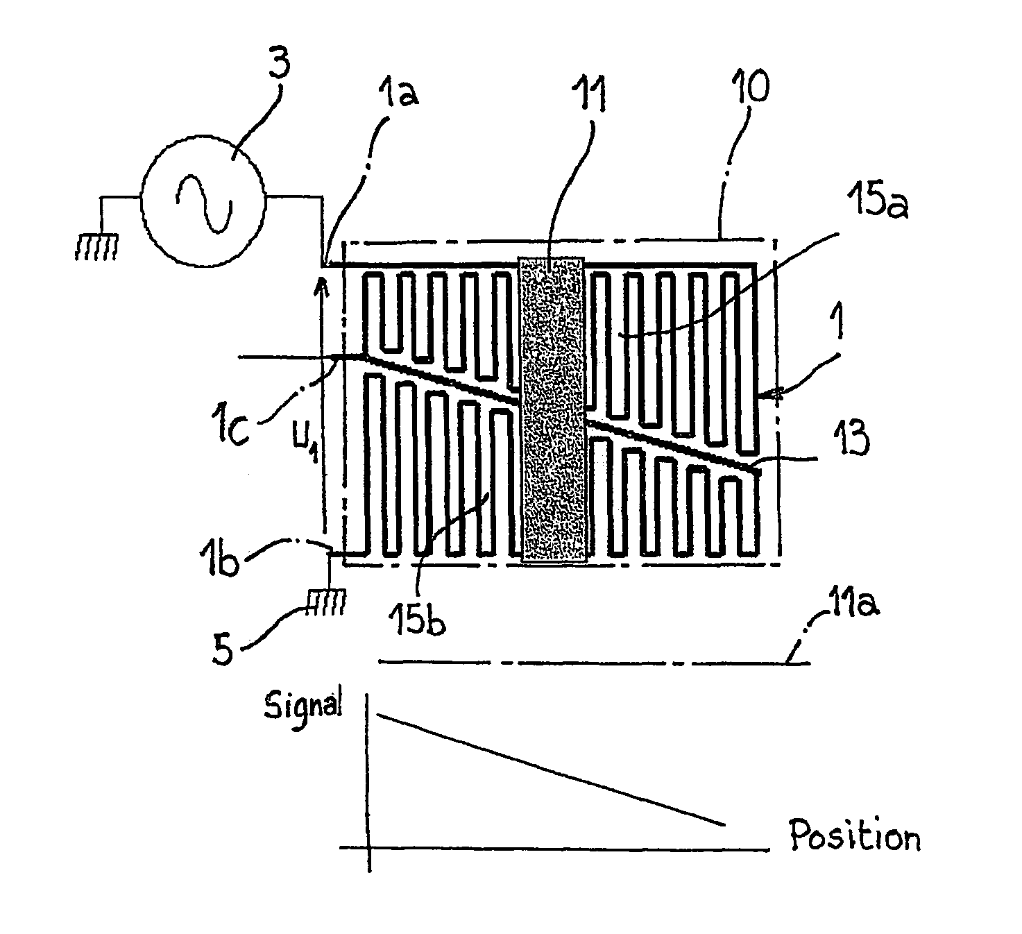
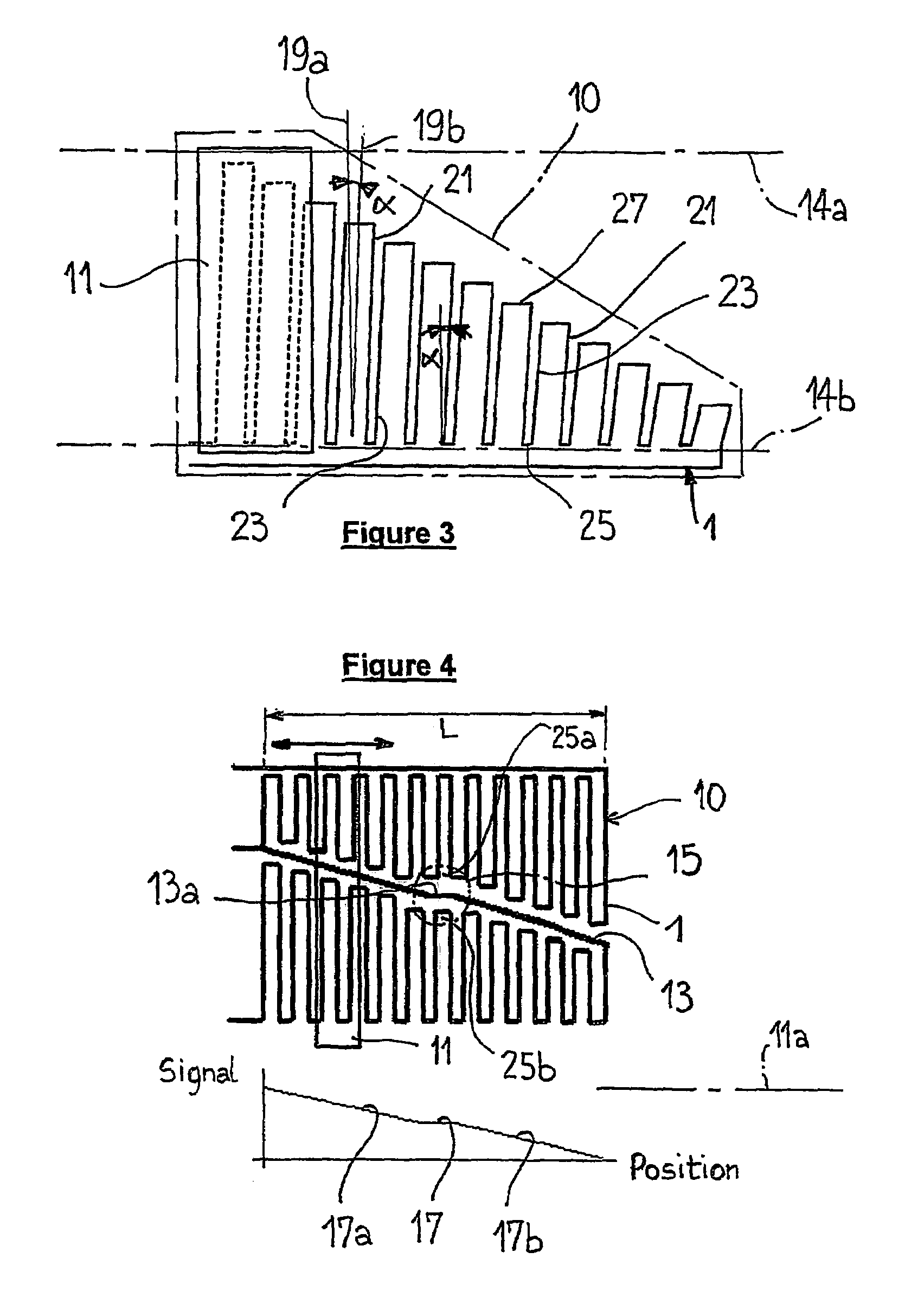
[0061]In what follows, it will be moreover considered that the physical characteristic of the electrical conductor 1, in the sensitive area 10 subjected to the effect of the magnet, which has to vary in order to allow the magnetoimpedance (or RMS) phenomenon to be used, is the impedance, and in particular the resistance R, of this conductor at the stimulation frequency.

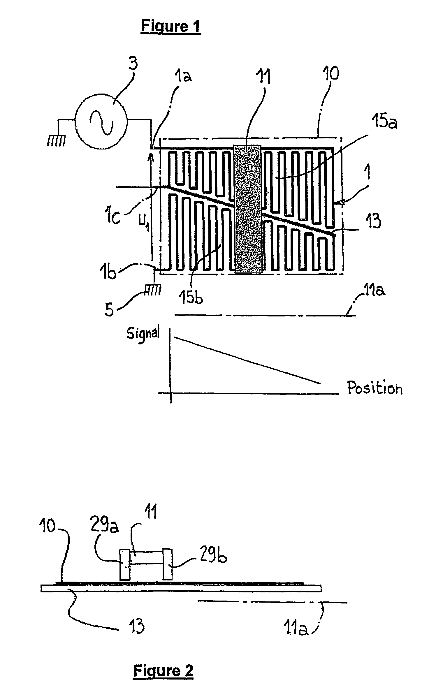
[0062]Before specifically dealing with the figures, it should also be noted that the position sensor of the invention, therefore favorably based on the variation in resistance R of an electrical conductor, in particular made of a paramagnetic or ferromagnetic material, and subjected to an AC voltage of frequency f, is in general described as follows:[0063]a permanent magnet, generating a known magnetic field, is moved opposite the elec...


PUM


Abstract

According to the intended use, an electrical conductor (1) having a magnetically sensitive surface (10) subjected to the magnetic force of a permanent magnet (11) is produced, the area of this surface varying according to its relative position with respect to the magnet, said relative position between the magnet and the magnetically sensitive surface is varied, which causes at least one physical characteristic of this conductor, to vary, and said variation in physical characteristic(s) of the electrical conductor is recorded, this variation being in correlation with the position of the magnet (11).

Description

BACKGROUND OF THE INVENTION[0001]The invention relates to the application of magnetoimpedance, also called here RMS (resistive magnetic saturation), in the field of sensors.[0002]More precisely, the invention relates here to the use of this magnetoimpedance on a contactless position sensor, and to the sensor itself.[0003]The physical phenomenon involved here is, in general, the following:[0004]an electrical conductor through which an AC electrical current flows sees this current distributed around the periphery of the conductor.[0005]This phenomenon is commonly called the skin effect.[0006]The depth of this skin is determined by the formula:[0007]δ=ρπμ0⁢μr⁢fwhere:[0008]δ is the skin depth;[0009]ρ is the resistivity of the conductor in ohms.meter;[0010]μ0 is the magnetic permeability of free space (4π×10−7);[0011]μr is the magnetic permeability of the material; and[0012]f is the frequency in hertz.[0013]Thus, the more the frequency f increases, the more the skin depth δ decreases.[00...

Claims


Application Information

Patent Timeline
IPC IPC(8): G01B7/14
CPCG01D5/145G01D5/2033
Inventor SERVEL, ERIC
Owner CONTINENTAL AUTOMOTIVE FRANCE
Why Eureka
Try Eureka