
Side-by-side hydrocarbon transfer system

Inactive Publication Date: 2010-09-14
SINGLE BUOY MOORINGS INC
View PDF12 Cites 14 Cited by
  • Summary
  • Abstract
  • Description
  • Claims
  • Application Information

AI Technical Summary

Benefits of technology

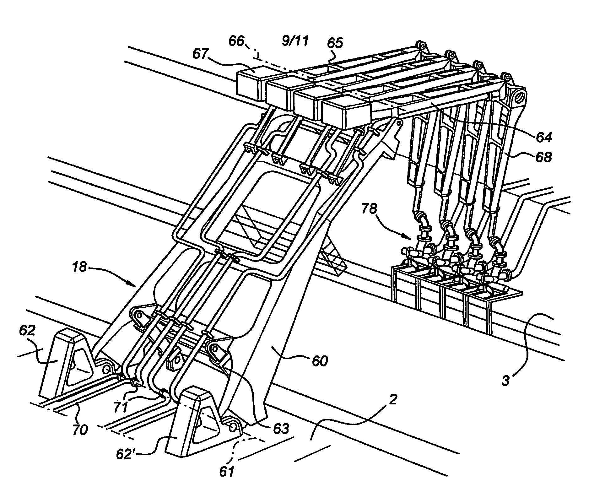
[0012]By using a transverse mooring arm which cannot rotate during use, the second vessel will not be displaced in a sideways direction when it moves in the length direction. The restoring force on the second vessel is exerted by the force element acting in the length direction of the vessels only, such that no sideways movement is caused. Hereby stable mooring in high sea states (for instance wave heights of 3-3.5 m) is possible while maintaining a minimum safety distance between the two vessels.
[0013]The transverse mooring arm may for instance have a length of 10 m or more, such that the distance between the two vessels can be of the same order of magnitude. Maintaining a relatively large distance between the vessels separates the stored volumes of hydrocarbons, which is favourable in case of an accident on one of the vessels, and avoids vessel interaction and wave build up between the vessels. The arm may be pivotable towards a parking position when no vessel is moored to the arm.
[0014]Because the mooring configuration according to the present invention is very stable and relative movements of the two vessels are relatively small, the hydrocarbon transfer arm or arms will be subject to relatively small excursions. The vertical duct of the hydrocarbon transfer arm can be a flexible duct, a rigid pipe or combinations thereof. Since the relative displacements of the vessels are limited, the vertical duct needs to be movable in a manner such as to accommodate these relatively small displacements. This results in a favourable force distribution and dynamics of the transfer ducts with resultant reduced wear and maintenance. In the length direction, the varying mooring positions due to drift of the moored second vessel or varying dimensions of the second vessel and varying positions of the loading-offloading manifold can be taken up by the displacement of the vertical duct.

Problems solved by technology

The known mooring system has as a disadvantage that the position of the tanker will change in a sideways direction upon an excursion in the length direction of the tanker relative to the permanently moored vessel.

Method used


Image

  • Side-by-side hydrocarbon transfer system
  • Side-by-side hydrocarbon transfer system
  • Side-by-side hydrocarbon transfer system

Examples


Embodiment Construction

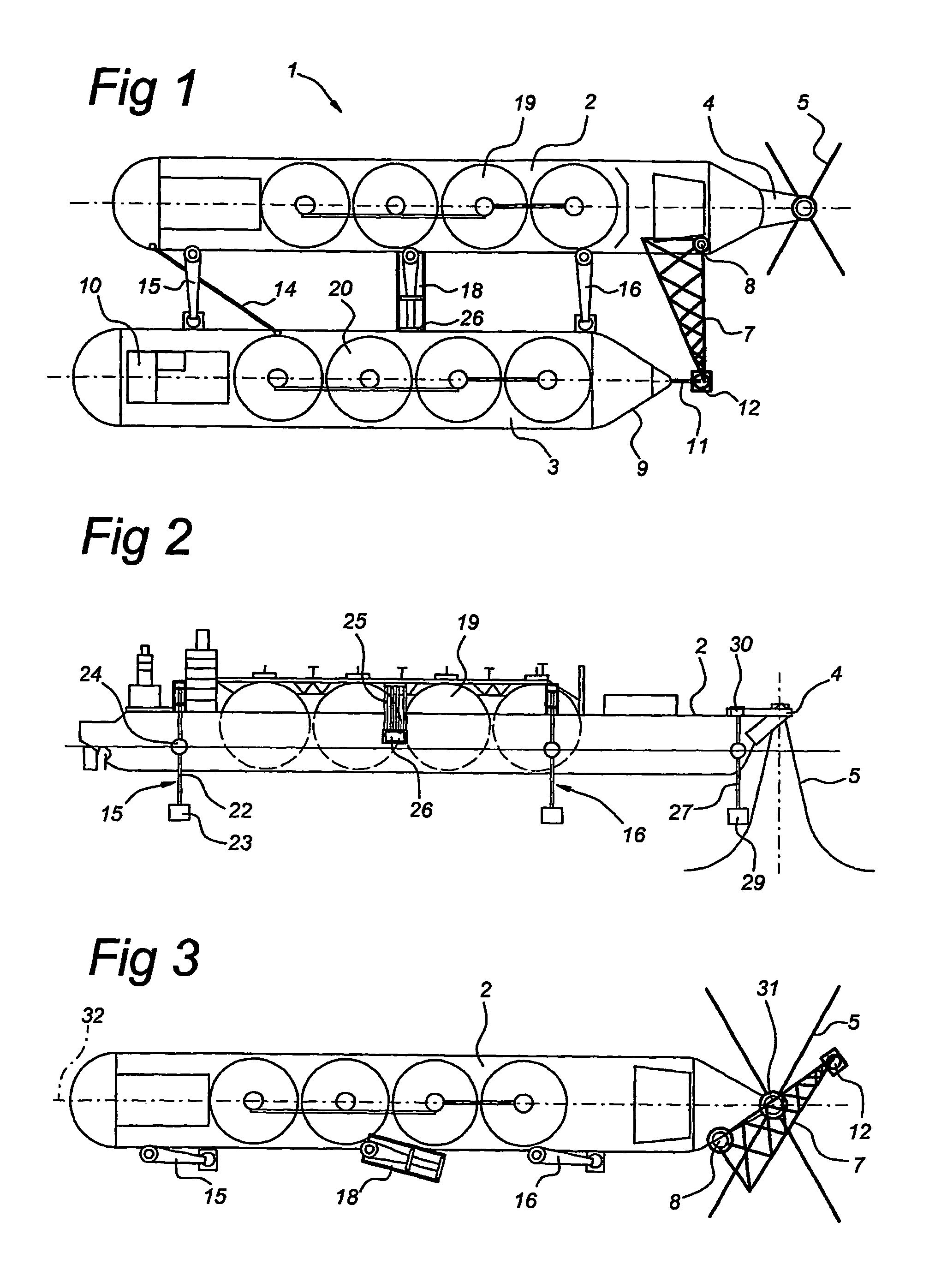
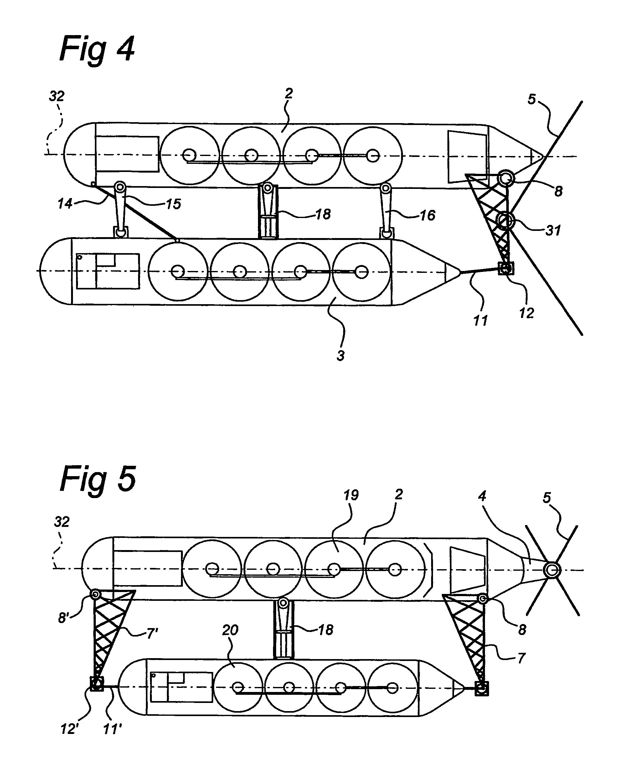
[0035]FIG. 1 shows the mooring system 1 comprising a floating storage and regasification unit (FSRU) 2 and moored alongside, a LNG carrier 3. The FSRU 2 is moored to the seabed via an external turret 4 that is anchored to the sea bed via anchor lines 5. A transverse mooring arm 7 is attached to the side of the FSRU. The mooring arm 7 can rotate around hinge point 8 to a parking position in which it is parallel to a length direction of the FSRU. In the operative position of the mooring arm 7, it is locked in position such that rotation around the hinge point 8 is not possible.

[0036]The carrier 3 is attached to mooring arm 7 at the bow 9 of the carrier, at the height of the centre line 10. A hawser 11 is attached to a pulling force element 12 for exerting a tensioning force on the hawser 11. The pulling force element 12 may be a constant tension winch, a hydraulic cylinder, a counterweight or other force elements suitable for exerting a force on the hawser 11. For reasons of safety an...


PUM

PropertyMeasurementUnit
Lengthaaaaaaaaaa
Lengthaaaaaaaaaa
Forceaaaaaaaaaa

Abstract

The invention relates to a mooring system with a first vessel for containing hydrocarbons having at its bow and / or stern a transverse arm and a fluid transfer mechanism of a duct connected to a tank on the first vessel and a coupling end for connecting to a second vessel. The second vessel is moored alongside the first vessel and is attached via at least one cable, extending from its bow in the length direction of the vessel, to a mooring end of the arm. The mooring end of the arm is situated at or near a longitudinal centerline of the second vessel. The arm, during use, is in a fixed position and a pulling force element is attached to the cable for applying a pulling force on the cable upon relative movement of the second vessel with respect to the arm. The force element allows a predetermined maximum displacement of the second vessel.

Description

BACKGROUND OF THE INVENTION[0001]1) Field of the Invention[0002]The invention relates to a mooring system comprising a first vessel for containing hydrocarbons having at its bow and / or stern a transverse arm and a fluid transfer means comprising a duct connected to a tank on the first vessel and a coupling end for connecting to a second vessel, the second vessel being moored alongside the first vessel and being attached via a cable, extending from its bow in the length direction of the vessel, to a mooring end of the arm, which mooring end of the arm is substantially situated at or near a longitudinal centreline of the second vessel.[0003]2) Description of the Related Art[0004]Such a mooring system is known from EP 1 413 511, which shows a side-by-side mooring configuration of a permanently moored vessel and a tanker vessel, which is attached to the permanently moored vessel via a transverse arm extending from the latter. The tanker is moored to the arm via an inelastic mooring line...

Claims


Application Information

Patent Timeline
IPC IPC(8): B63B3/24B63B21/04B63B21/50B63B27/24
CPCB63B21/04B63B21/50B63B27/24
Inventor POLDERVAART, LEENDERTPOLLACK, JACKWILLE, HEINOOMEN, HEIN
Owner SINGLE BUOY MOORINGS INC
Learn More