Ignition coil

a technology of ignition coil and secondary output terminal, which is applied in the direction of continuously variable inductance/transformer, mechanical apparatus, machines/engines, etc., can solve the problems of unbalanced output, unbalanced output, and inability to stabilize secondary output in low-speed ranges, etc., and achieve the effect of balanced outputs

Active Publication Date: 2010-09-14
TOYO DENSO CO LTD +1
View PDF8 Cites 6 Cited by
  • Summary
  • Abstract
  • Description
  • Claims
  • Application Information

AI Technical Summary

Benefits of technology

[0013]The present invention provides an ignition coil of a dual ignition type that can prevent outputs from becoming unbalanced due to a difference in floating capacitance on wiring that connects secondary output terminals and ignition plugs together, thus realizing balanced outputs.
[0014]Also, the present invention provides an ignition coil of which output from secondary coils is stable, and in particular an ignition coil of a dual ignition type that can prevent interference of parallel-connected primary coils and thus prevent a decrease in output in a low-speed range and obtain stable output.

Problems solved by technology

However, according to the conventional ignition coil of the dual ignition type, outputs from the two secondary output terminals tend to be different due to a difference in the layout of the ignition plugs.
Specifically, in the case where one of the secondary output terminals is directly connected to one ignition plug, and the other one of the secondary output terminals is connected to the other ignition plug in the same cylinder via a high tension cord, outputs tend to become unbalanced due to a difference in floating capacitance on wiring extending from the secondary output terminals to the ignition plugs.
Also, the ignition coil of the dual ignition type shown in FIG. 14 has the problem that secondary output in a low-speed range is unlikely to be stable, and the ignition coil shown in FIG. 15 has the problem that interference of the primary coils occurs due to back electromotive force, resulting in output from the secondary coils decreasing.
Thus, if the primary coils comprised of the parallel-connected two coils as shown in FIG. 15 are applied to the ignition coil of the dual ignition type, predetermined high-voltage outputs cannot be applied to the two secondary output terminals, and this will bring about a great loss of output from an engine as a whole.

Method used


Image

  • Ignition coil
  • Ignition coil
  • Ignition coil

Examples


first embodiment

[0065]the present invention will now be described in detail with reference to the drawings.

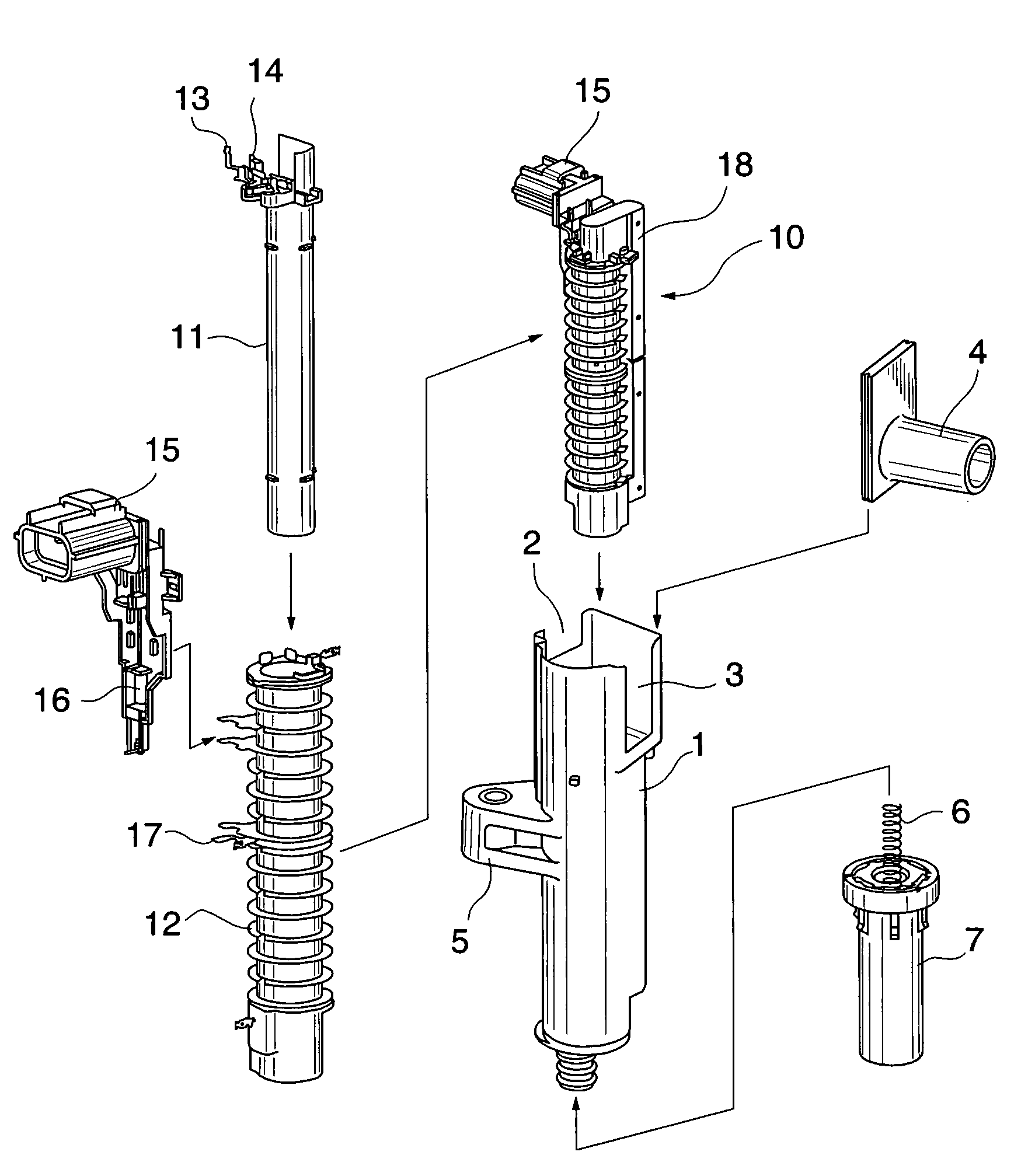
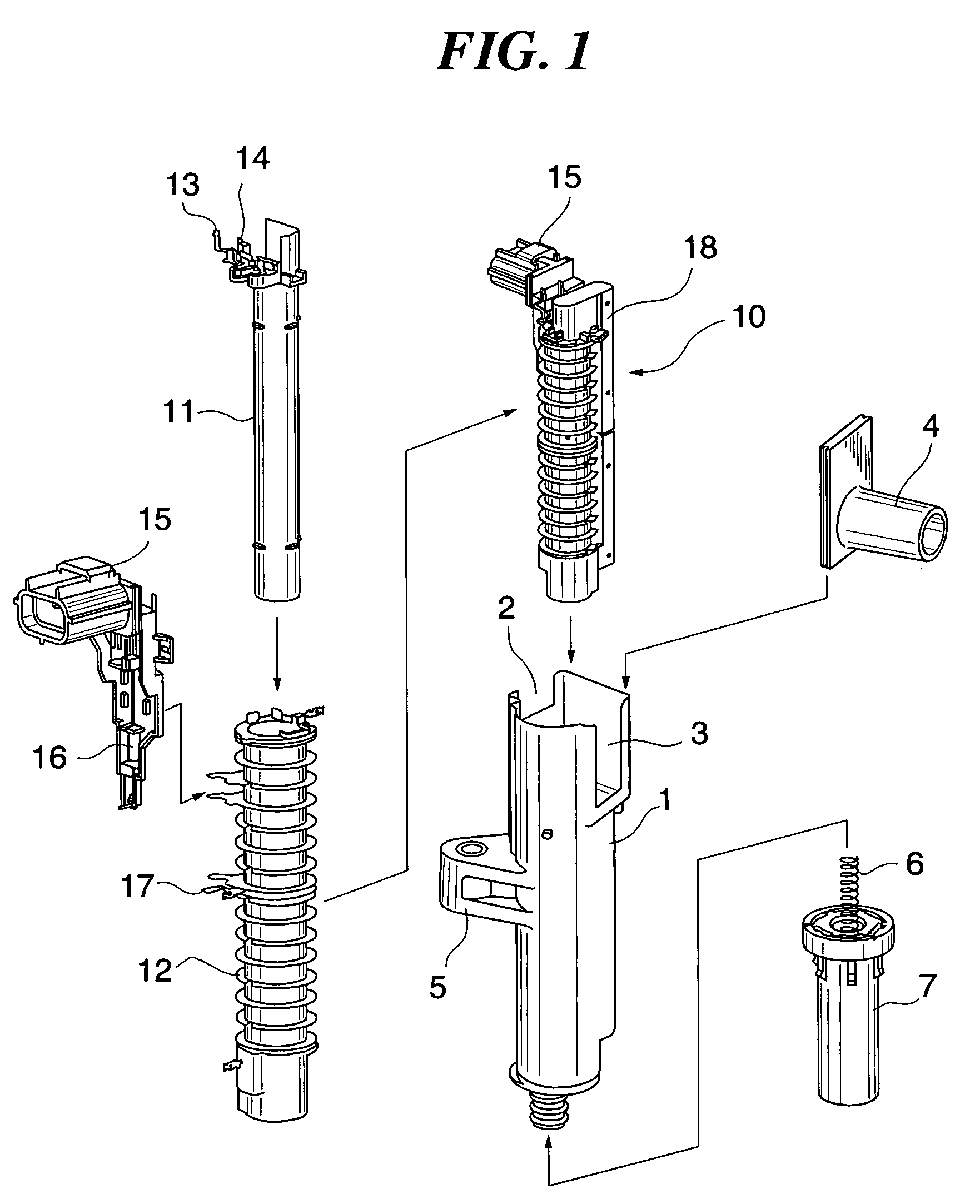
[0066]FIG. 1 is an assembly diagram showing an ignition coil for an internal combustion engine according to the first embodiment.

[0067]As shown in FIG. 1, the ignition coil is of a dual ignition type having two secondary output terminals, and is comprised mainly of a housing 1 as a coil case, and a coil assembly 10 fitted into the housing 1.

[0068]The coil assembly 10 is comprised of a substantially cylindrical primary coil bobbin 11 around which a primary coil (not shown) is wound, and a substantially cylindrical secondary coil bobbin 12 around which secondary coils (not shown) are wound and of which diameter is larger than the diameter of the primary coil bobbin 11. The secondary coil bobbin 12 around which the secondary coil is wound is disposed outside and concentrically with the primary coil bobbin 11 around which the primary coil is wound. The primary coil and the secondary coils thus for...

second embodiment

[0111]Next, a detailed description will be given of the present invention with reference to the drawings.

[0112]FIG. 6 is an assembly diagram showing a coil case applied to an ignition coil for an internal combustion engine according to the second embodiment, and FIG. 7 is a perspective view showing a coil assembly fitted into the coil case in FIG. 6. The ignition coil according to the present embodiment is of a dual ignition type having two secondary output terminals, and is comprised mainly of a housing 101 as the coil case in FIG. 6, and a coil assembly 110 in FIG. 7 fitted into the housing 101.

[0113]As shown in FIG. 6, a cut portion 102 with which a connector 115 (see FIGS. 7 and 8 referred to later) that supports primary terminals of the coil assembly is to be engaged is provided at an opening end of an upper portion of the housing 101. A cut portion 103 with which a high-tension (H / T) tower 104 as a take-out end for secondary output from the coil assembly is to be engaged is pr...


PUM

PropertyMeasurementUnit
widthaaaaaaaaaa
winding widthaaaaaaaaaa

Abstract

An ignition coil of a dual ignition type that can prevent outputs from becoming unbalanced due to a difference in floating capacitance on wiring that connects secondary output terminals and ignition plugs together, thus realizing balanced outputs. A coil assembly housed in a housing as a coil case has a primary coil and secondary coils disposed concentrically with the primary coil. The secondary coils are comprised of two coils wound in opposite directions with the center of winding width being a boundary. The center of the winding width of the primary coil is shifted from the center of the winding width of the secondary coils by a predetermined width so as to balance outputs from the two secondary coils. A casting material is filled into a gap between the housing and the coil assembly and gaps which the coil assembly has.

Description

BACKGROUND OF THE INVENTION[0001]1. Field of the Invention[0002]The present invention relates to an ignition coil of a dual ignition type that is applied to a cylinder having two ignition plugs, and in particular to an ignition coil that has an output terminal mounted on a plug hole of an engine and directly connected to one ignition plug, and an output terminal connected to the other ignition plug in the same cylinder via a high tension cord.[0003]2. Description of the Related Art[0004]In internal combustion engines such as vehicle engines, an ignition coil and an ignition plug are used as, for example, detonators that burn gasoline as fuel.[0005]As an example of an ignition coil, there is known an ignition coil of a dual ignition type that is applied to a cylinder having two ignition plugs.[0006]Examples of publications of prior arts relating to an ignition coil of a dual ignition type, a diagnostic apparatus therefor, or the like include Japanese Examined Patent Publication (Koko...

Claims


Application Information

Patent Timeline
Patent Type & Authority Patents(United States)
IPC IPC(8): H01F27/02F02P3/02H01F38/12H01F27/30H01F17/06H01F21/04
CPCH01F27/022H01F38/12
Inventor MATSUBAYASHI, SHUICHIHIRAYAMA, IKUOKOJIMA, MASAMITAUCHI, TAKASHI
Owner TOYO DENSO CO LTD
Why Eureka
Try Eureka