Two-step roller finger cam follower assembly having a follower travel limiter

a follower assembly and roller finger technology, applied in the direction of engine components, mechanical equipment, machines/engines, etc., can solve the problems of engine noise and error, hla will not recover, and engulf air, and achieve the effect of preventing excessive leakage of the associated hydraulic lash adjuster

Active Publication Date: 2010-09-21
DELPHI TECH IP LTD
View PDF3 Cites 29 Cited by
  • Summary
  • Abstract
  • Description
  • Claims
  • Application Information

AI Technical Summary

Benefits of technology

[0007]Briefly described, a two-step roller finger follower assembly is provided for use in conjunction with a camshaft of an internal combustion engine, wherein the camshaft has at least one first lobe and at least one second lobe. Preferably, the first lobe is for low valve lift and the second lobe is for high valve lift. The roller finger follower assembly comprises a follower body for engaging the first cam lobe and includes a central aperture. A high-lift follower is disposed in the central aperture for engaging the second cam lobe, and a limiting stop is disposed on the follower body for engaging a feature on the high lift follower to limit travel of the follower body with respect to the high-lift follower. The limiting stop prevents overtravel of the follower body during valve-deactivation mode of the assembly, thus preventing excessive leak down of an associated hydraulic lash adjuster.

Problems solved by technology

When the amount of leak down exceeds the available volume of oil within the HLA's oil reserve chamber, the HLA will not recover and will engulf air.
This causes problems with its hydraulic stiffness and can result in engine noise and error in an ensuing valve lift event.

Method used


Image

  • Two-step roller finger cam follower assembly having a follower travel limiter
  • Two-step roller finger cam follower assembly having a follower travel limiter
  • Two-step roller finger cam follower assembly having a follower travel limiter

Examples


first embodiment

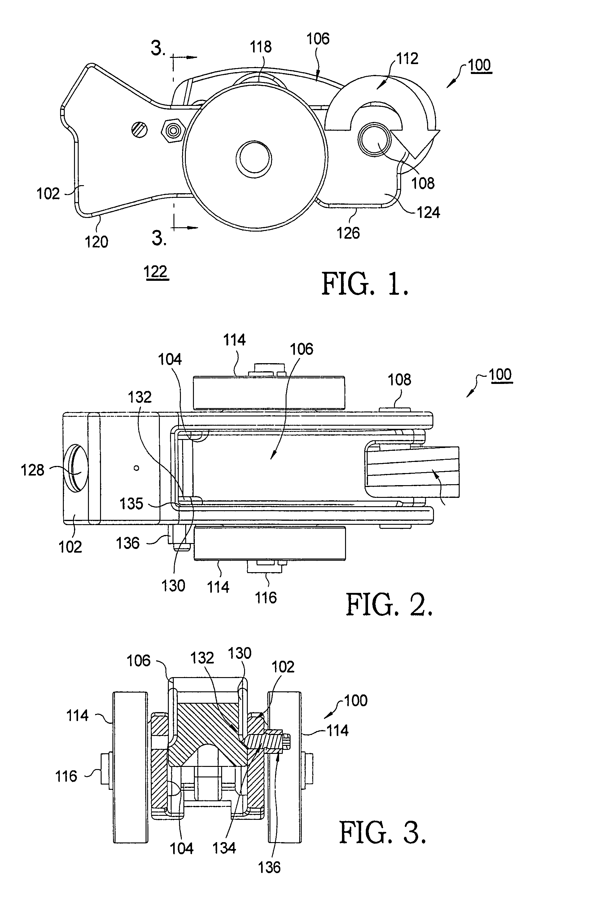
[0016]In accordance with the invention and a first embodiment thereof, high lift follower 106 is provided with a relief 130 along one or both sides thereof, creating a land 132 that preferably is sloped with respect to the direction of travel of follower 106. A limiting stop 134 comprising a screw is threadedly received in a threaded bore in body 102 and extends into central aperture 104 and relief 130 so as to engage land 132 at a predetermined limit of rotational travel of follower 106 in direction 112 with respect to body 102. Preferably, limiting stop screw 134 is tapered at the inner end thereof 135 to permit adjustment of the engagement point with land 132 and thus adjustment of the limit of rotational travel of follower 106. A lock nut 136 may be provided to secure screw 134 in a set position as desired.

[0017]Referring now to FIGS. 4-6, a second two-step roller finger follower assembly 200 illustrates additional embodiments of a limiting stop in accordance with the invention....

embodiment 100

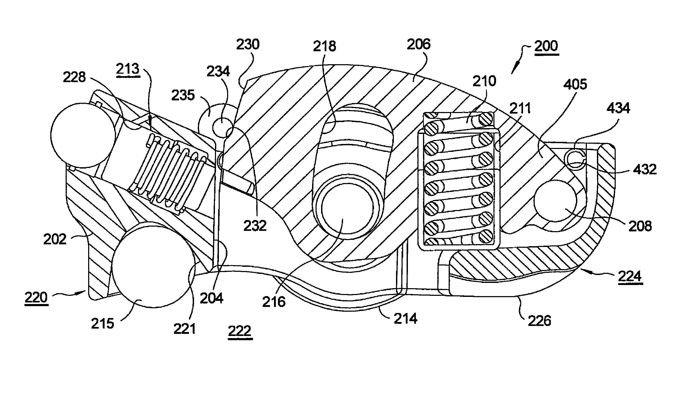
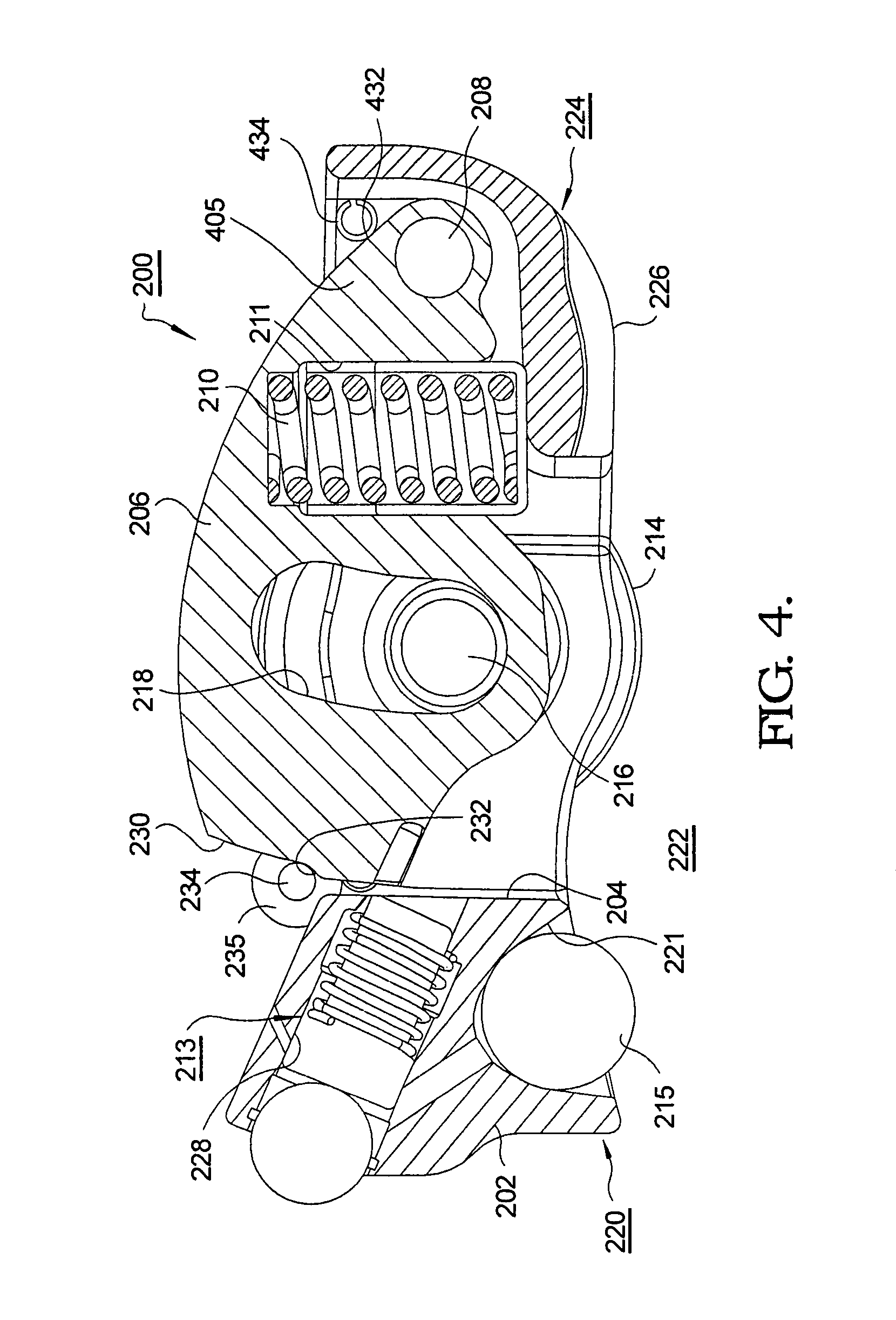
[0018]Assembly 200 is mechanically essentially identical with assembly 100 except that a compression spring 210 in a well 211 formed in high-lift follower 206 replaces torsion spring 110 in embodiment 100. Also note that a latching mechanism 213 of a similar type that would be used in assembly 100, and HLA head 215 are shown.

[0019]Assembly 200 comprises a follower body 202 having a central aperture 204 for receiving a high-lift follower 206 that is pivotably secured to body 202 via a pin 208. A roller 214 is mounted on an axle 216 that is mounted, preferably on needle bearings (not shown), in a bore through the sidewalls of body 202. Axle 216 passes through an arcuate slot 218 in high-lift follower 206, permitting the follower to rotate freely about pin 208. A first end 220 of body 202 includes a hemispherical socket 221 for pivotably receiving the spherical head 215 of a hydraulic lash adjuster upon which follower assembly 200 is mounted in an engine 222. A second end 224 of body 2...

second embodiment

[0020]In accordance with the invention and a second embodiment thereof, high lift follower 206 is provided with a relief 230 along the latching end thereof, creating a land 232. A limiting stop 234 comprising a roll pin is received in a boss 235 formed in body 202 and extends into relief 230 so as to engage land 232 at a predetermined limit of rotational travel of follower 206 with respect to body 202.

[0021]Referring now to FIG. 5, a third embodiment is similar to the just-described second embodiment except that relief 330 and land 332 are formed along the side 333 of follower 306. Boss 335 is placed accordingly such that limiting stop 334, such as a roll pin, extends into relief 330 and engages land 332, thereby limiting the rotation of follower 306 within body 302.


PUM


Abstract

A two-step roller finger follower assembly for use in conjunction with a camshaft of an internal combustion engine, wherein the camshaft has at least one first lobe and at least one second lobe. The roller finger follower assembly comprises a follower body for engaging the first cam lobe and having a central aperture, a follower pivotably disposed on the follower body in the central aperture for engaging the second cam lobe, and a limiting stop disposed on the follower body for engaging a feature on the follower to limit travel of the follower body with respect to the follower. The limiting stop prevents overtravel of the follower body during valve-deactivation mode of the assembly, thus preventing excessive leak down of an associated hydraulic lash adjuster.

Description

TECHNICAL FIELD[0001]The present invention relates to roller finger follower assemblies used for valve actuation in overhead cam type internal combustion engines; more particularly to a two-step roller finger follower assembly having a high lift cam follower that is pivotably mounted in a follower body; and most particularly, to such an assembly wherein a limiting stop limits the travel of the high lift cam follower when the two-step roller finger follower assembly is in valve-deactivation mode.BACKGROUND OF THE INVENTION[0002]Roller Finger Followers (RFF) are widely used in overhead cam internal combustion engines to sequentially open and close the cylinder intake and exhaust valves. In a typical application, the RFF serves to transfer and translate rotary motion of a cam shaft lobe into a pivotal motion of the RFF to thereby open and close an associated valve.[0003]It is known that, for a portion of the duty cycle of a typical multiple-cylinder engine, the performance load can be ...

Claims


Application Information

Patent Timeline
Patent Type & Authority Patents(United States)
IPC IPC(8): F01L1/18
CPCF01L1/185F01L13/0036F01L13/0015Y10T74/2107F01L2001/186
Inventor FISCHER, THOMAS H.LIPINSKI, ANDREW J.FERNANDEZ, HERMES A.KUNZ, TIMOTHY W.ROE, RICHARD B.
Owner DELPHI TECH IP LTD
Why Eureka
Try Eureka