
Electronic table top board game

a table top board game and electronic technology, applied in the field of board games, can solve the problems of limited movement and interaction of game pieces, lack of prior art example that does not provide unique elements of unicycle movement, etc., and achieve the effect of rotating in syn

Inactive Publication Date: 2010-09-21
JOLICOEUR PIERRE
View PDF3 Cites 5 Cited by
  • Summary
  • Abstract
  • Description
  • Claims
  • Application Information

AI Technical Summary

Benefits of technology

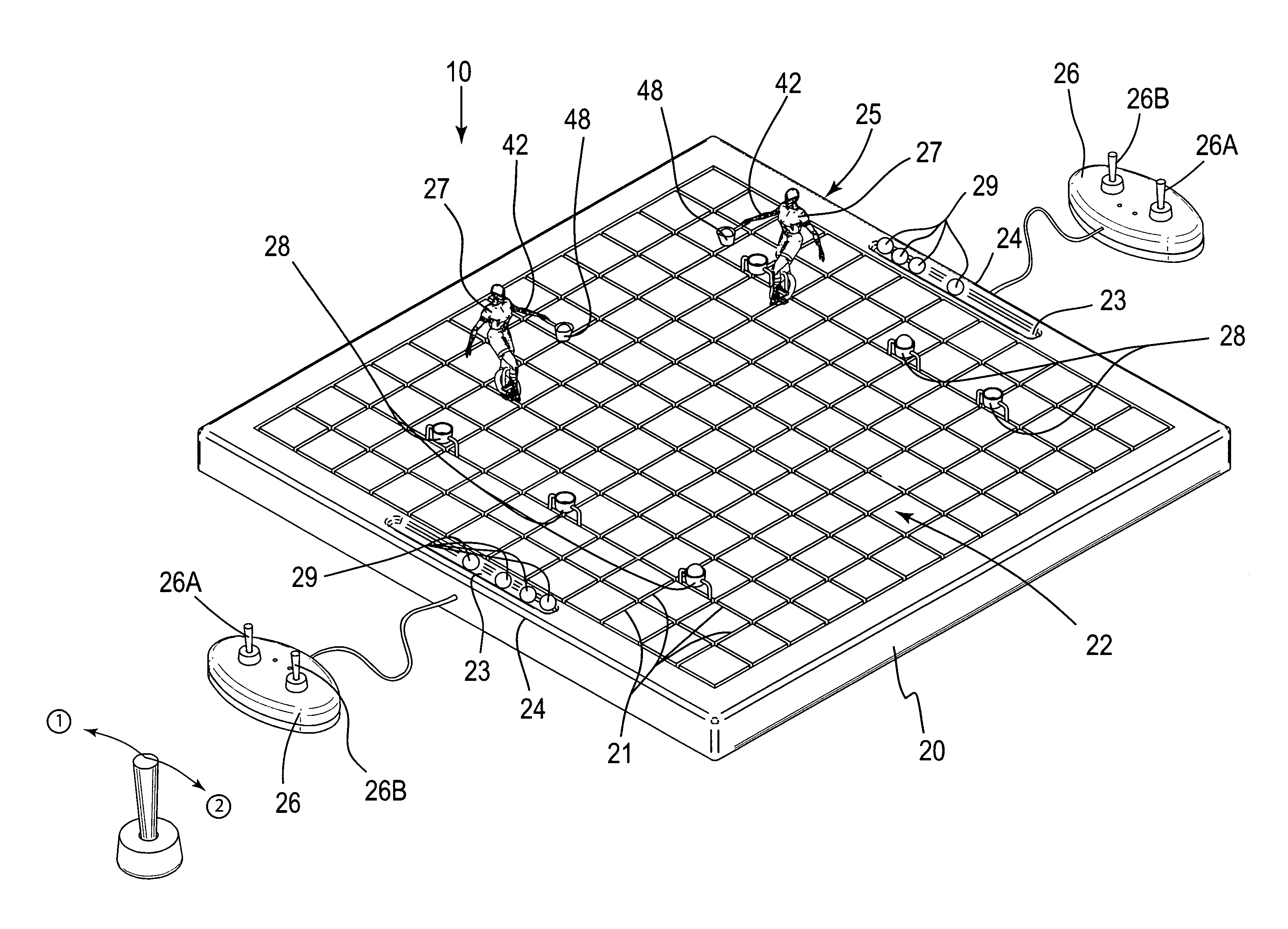
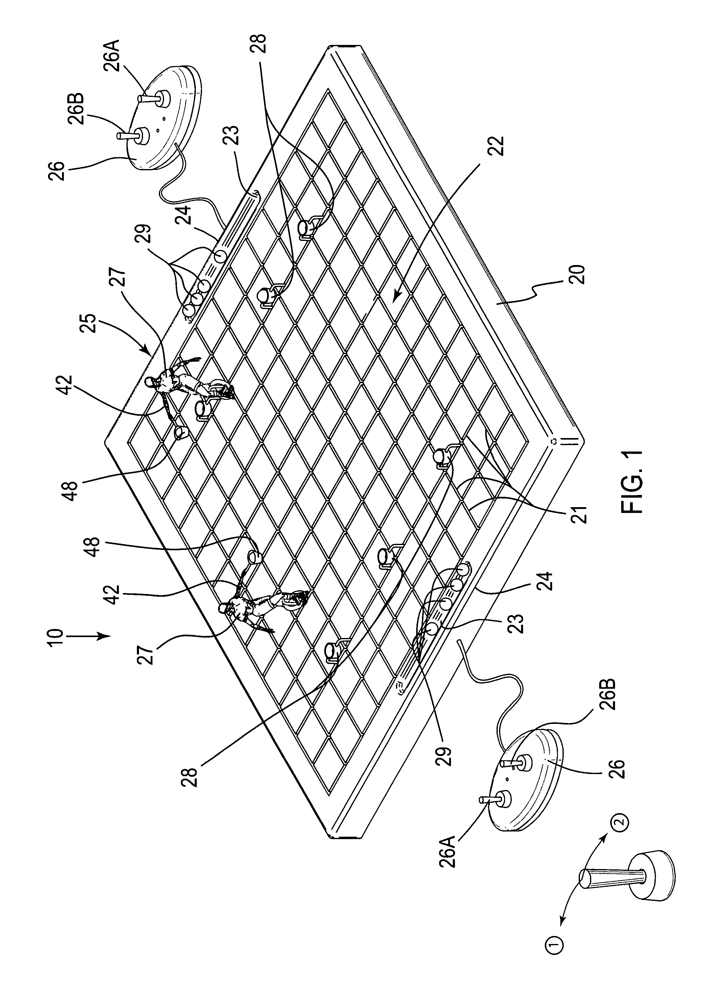
[0013]The device further includes a plurality of controls operably coupled to the game board, and a plurality of mobile game pieces selectively positional along the grooves. A plurality of target zones is manually and removably anchored to the game board and spaced along the grooves. A plurality of projectiles are associated with each of the game pieces and are conveniently stored within the notches. Such game pieces further include a plurality of conductive leads in electrical communication with the grooves, and first and second switches directly coupled to the leads and the processor (herein described below) respectively. First and second output signals effectively instruct the first and second switches to independently toggle between open and closed positions such that each of the game pieces simultaneously receives the first and second output signals from each of the controllers based upon the user input.
[0014]The device further includes a mechanism for independently displacing each of the game pieces along the grooves based upon a user input triggered through an associated one of the controllers. Such a game piece displacing mechanism effectively maintains direct contact with a bottom surface of the grooves during playing conditions. The game piece displacing mechanism conveniently includes a processor, and a memory electrically coupled thereto. Such a memory includes software instructions that effectively cause each of the game pieces to be responsive to the user input. Such software instructions include and execute a control logic algorithm that includes the steps of determining whether a first one of the controls has been engaged by an associated one of the players, determining a direction in which the first control has been adapted, determining a magnitude in which the first control has been adapted, and generating a first output signal for effectively instructing the game pieces to travel along the grooves based upon the determined direction and magnitude of the first control adaptation.
[0017]The arm pivoting mechanism further includes first and second beveled gears directly connected to each other. Such a first beveled gear is directly anchored to a top end of the drive shaft and further is rotatable in sync therewith. A driven motor is electrically coupled to one of the first and second switches. A rectilinear shaft advantageously protrudes outwardly from each of the game pieces and has a basket directly attached to a distal end thereof. Such a basket conveniently holds one of the projectiles therein during operating conditions. An arcuately shaped pivot arm has opposed ends pivotally anchored to the driven motor and a proximal end of the shaft respectively. Such a pivot arm advantageously rotates along a second arcuate path that has a radius smaller than a radius of the first arcuate path such that the rectilinear arm effectively rotates in sync therewith. The first beveled gear is driven by the drive shaft along a horizontal plane and thereby effectively causes the second beveled gear to rotate along a vertical plane in such a manner that the rectilinear arm simultaneously rotates and pivots based upon the user input.

Problems solved by technology

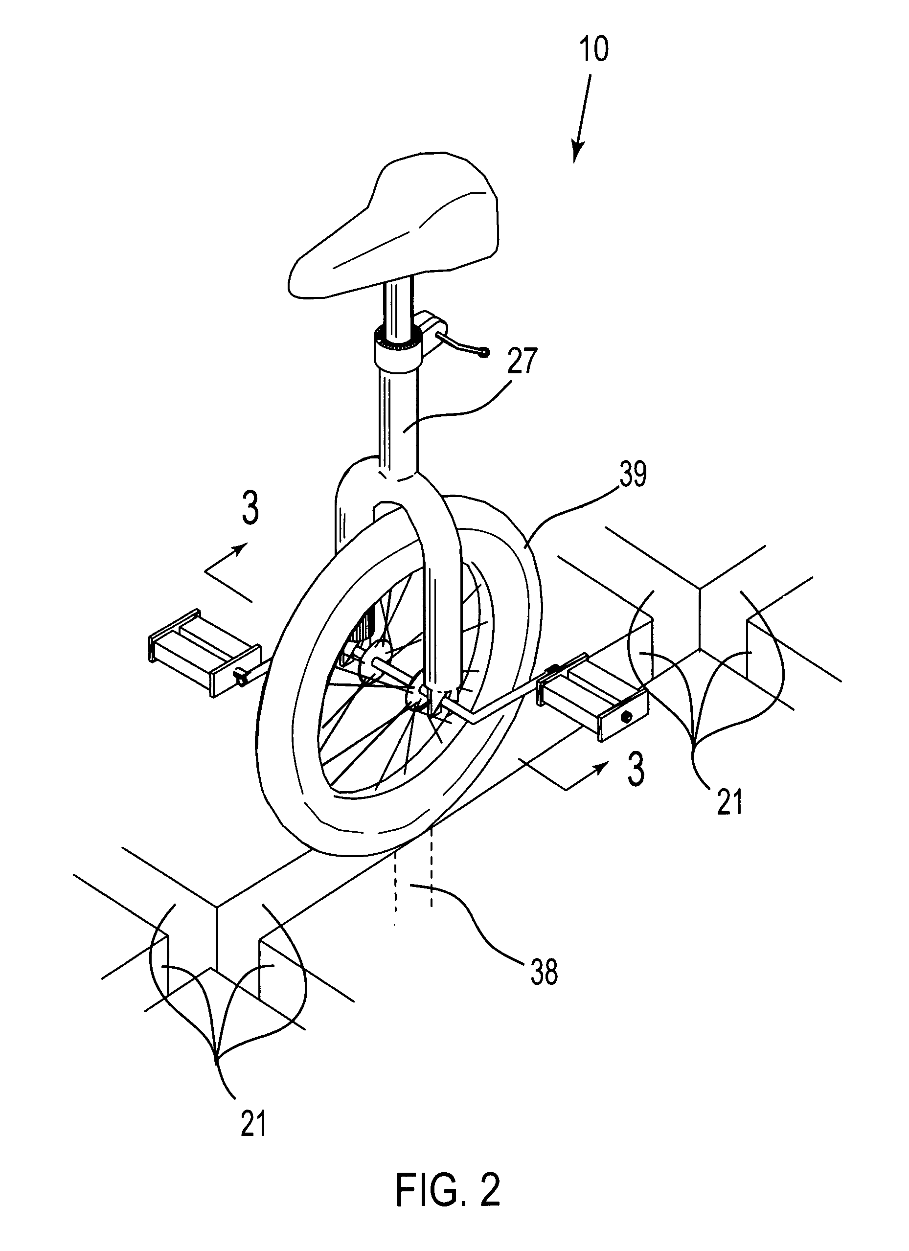
Unfortunately, this prior art example does not provide the unique elements of unicycle movement combined with an independently operable means of propelling a projectile toward a target.
Unfortunately, this prior art example provides a limited amount of movement and interaction of the game pieces and also does not provide the unique elements of unicycle movement.

Method used


Image

  • Electronic table top board game
  • Electronic table top board game
  • Electronic table top board game

Examples


Embodiment Construction

[0024]The present invention will now be described more fully hereinafter with reference to the accompanying drawings, in which a preferred embodiment of the invention is shown. This invention may, however, be embodied in many different forms and should not be construed as limited to the embodiment set forth herein. Rather, this embodiment is provided so that this application will be thorough and complete, and will fully convey the true scope of the invention to those skilled in the art. Like numbers refer to like elements throughout the figures.

[0025]The device of this invention is referred to generally in FIGS. 1-3 by the reference numeral 10 and is intended to provide an electronic table top board game. It should be understood that the device 10 may be used to provide enjoyment to many different types of users and should not be limited to providing enjoyment only to those types of users described herein.

[0026]Referring initially to FIG. 1, the device 10 includes a game board 20 th...


PUM


Abstract

A game board has grooves aligned parallel to X and Y axes that define travel paths along pre-determined directions covering a surface area thereof. Notches are formed along end regions oppositely spaced from each other along an outer periphery of the board. Controllers are coupled to the board, and game pieces are positional along the grooves. Target zones are anchored to the board and spaced along the grooves. Projectiles associated with the game pieces are stored within the notches. A mechanism displaces each of the game pieces along the grooves based upon a user input through an associated controller, and maintains contact with a bottom surface of the grooves. A mechanism rotates one arm of each of the game pieces such that each player tosses one of the projectiles along a travel path terminating at one of the target zones.

Description

CROSS REFERENCE TO RELATED APPLICATIONS[0001]This application claims the benefit of U.S. Provisional Application No. 60 / 781,195, filed Mar. 13, 2006, of which the entire disclosures are incorporated herein by reference.STATEMENT REGARDING FEDERALLY SPONSORED RESEARCH OR DEVELOPMENT[0002]Not Applicable.REFERENCE TO A MICROFICHE APPENDIX[0003]Not Applicable.BACKGROUND OF THE INVENTION[0004]1. Technical Field[0005]This invention relates to board games and, more particularly, to an electronic table top board game for providing user enjoyment.[0006]2. Prior Art[0007]For centuries, games have been a favorite pastime of adults as well as children. In fact, the earliest form of the familiar checkers can be traced to the Egyptians as early as 600 B.C. Traditional board, card and trivia games continue to flourish, despite the foreboding in recent years that these would suffer in popularity from the onslaught of computer, video and handheld forms of play. Culture watchers further stipulate tha...

Claims


Application Information

Patent Timeline
IPC IPC(8): A63F9/24
CPCA63F7/0652A63F7/0664A63F7/2472A63F7/26A63F7/0612A63F7/249
Inventor JOLICOEUR, PIERRE
Owner JOLICOEUR PIERRE
Learn More