Rolling element accommodating belt for linear guide apparatus and linear guide apparatus
a technology of rolling element and accommodating belt, which is applied in the direction of bearings, shafts and bearings, bearings, etc., can solve the problems of troublesome and difficult automation, troublesome mounting operation, and difficulty in mounting, and achieve the effect of restricting swing and facilitating mounting of rolling elements
- Summary
- Abstract
- Description
- Claims
- Application Information
AI Technical Summary
Benefits of technology
Problems solved by technology
Method used
Image
Examples
first embodiment
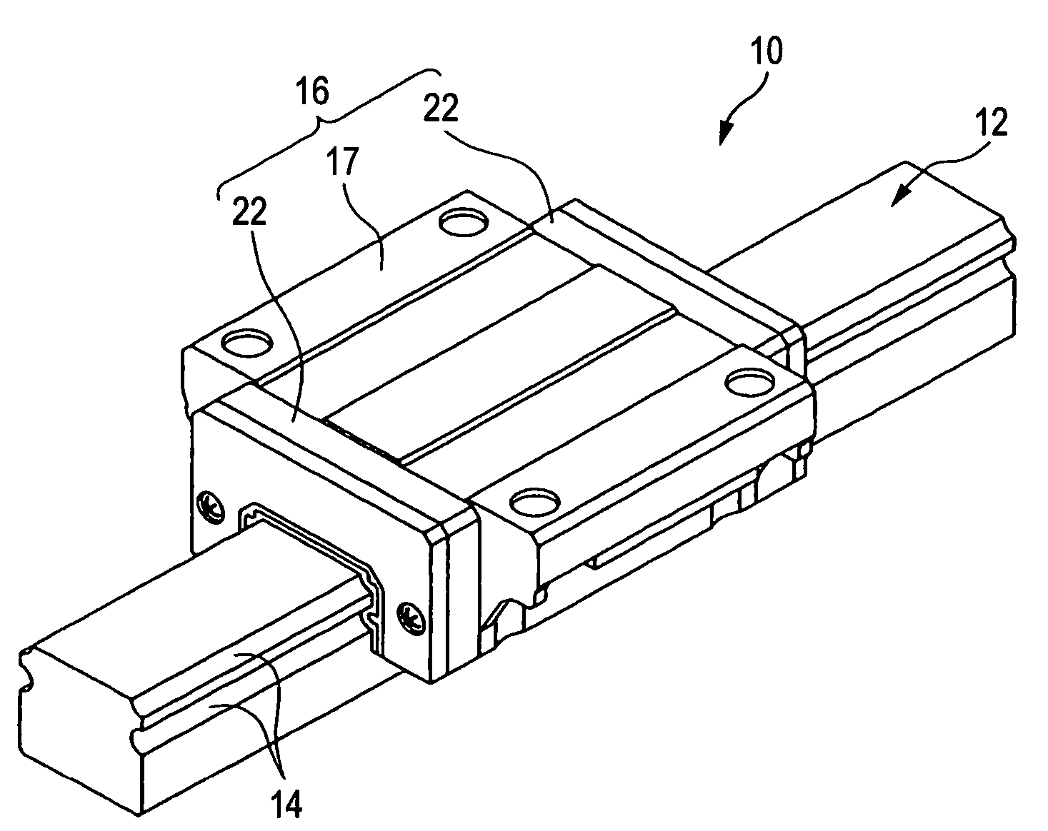
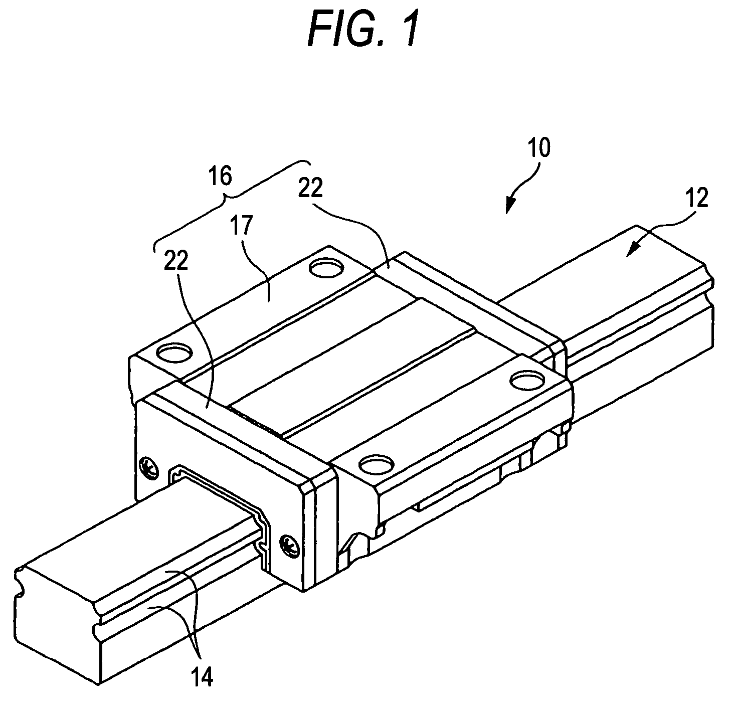
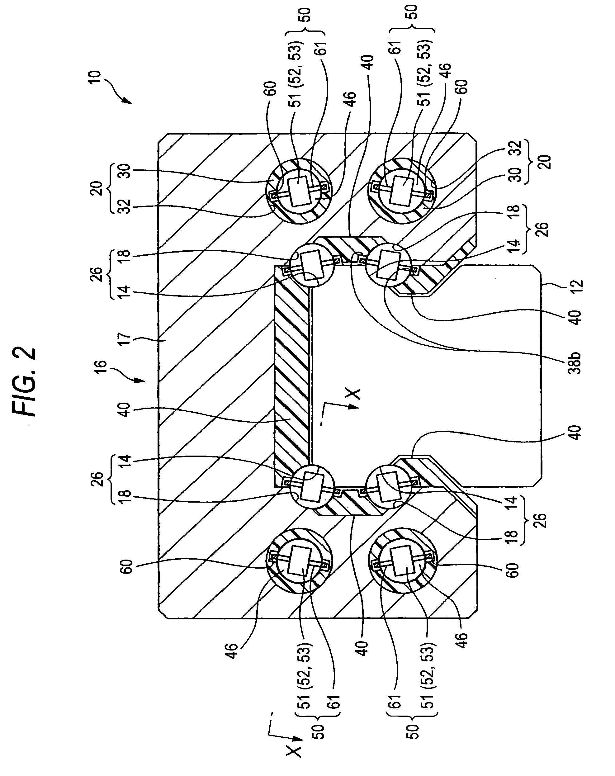
[0287]FIG. 1 is a perspective view of a linear guide according to the first embodiment of a linear guide apparatus provided with a rolling element accommodating belt for use therein according to this invention. FIG. 2 is a view for explaining the cross section of a slider of the linear guide in FIG. 1. FIG. 3 is a sectional view taken in line X-X in the linear guide in FIG. 2.
[0288]As seen from FIGS. 1 and 2, a linear guide apparatus 10 includes a guide rail 12 having rolling element guiding faces 14 and a slider 16 which straddles the guide rail 12 so that the slider is movable relatively to the guide rail 12.
[0289]The guide rail 12 is formed in a square sectional shape, and has four strips of rolling element guiding faces 14, two for each of both sides which are formed linearly in the longitudinal direction.
[0290]The slider 16, as seen from FIG. 1, includes a slider body 17 and end caps 22 mounted at both ends in an axial direction of the slider body 17. The axially continuous sha...
second embodiment
[0338]Next, an explanation will be given of the linear guide apparatus according to a second embodiment of this invention. In this embodiment, the configuration is the same as the first embodiment except that the structure of the rolling element accommodating belt is partially different. Therefore, only the difference on the rolling element accommodating belt will be explained, and the other will be not be explained.
[0339]As seen from FIG. 12, a rolling element accommodating belt 72 has two kinds of spacers, i.e. a spacer 54 and a spacer 55. These spacers are alternately arranged in the arrangement direction of the balls so that two kinds of rolling element accommodating portions, i.e. a rolling element accommodating portion A and a rolling element accommodating portion B are alternately formed in the arrangement direction of the balls 46. The rolling element accommodating belt 50 according to this embodiment is different from that in the first embodiment in that these spacers 54, 5...
third embodiment
[0345]Next, an explanation will be given of the linear guide apparatus according to a third embodiment of this invention. In this embodiment, the configuration is the same as the embodiments described above except that the structure of the rolling element accommodating belt is partially different. Therefore, only the difference on the rolling element accommodating belt will be explained, and the other will be not be explained.
[0346]As seen from FIG. 13, a rolling element accommodating belt 73 is different from the rolling element accommodating belt 50 according to the first embodiment in that it has two kinds of spacers, i.e. a spacer 56 and a spacer 57; and these spacers are alternately arranged in the arrangement direction of the balls so that two kinds of rolling element accommodating portions, i.e. a rolling element accommodating portion A and a rolling element accommodating portion B are alternately formed in the arrangement direction of the balls 46.
[0347]The spacers 56, 57 ha...
PUM
 Abstract
Description
Claims
Application Information
 - R&D
- Intellectual Property
- Life Sciences
- Materials
- Tech Scout
- Unparalleled Data Quality
- Higher Quality Content
- 60% Fewer Hallucinations
Browse by: Latest US Patents, China's latest patents, Technical Efficacy Thesaurus, Application Domain, Technology Topic, Popular Technical Reports.
© 2025 PatSnap. All rights reserved.Legal|Privacy policy|Modern Slavery Act Transparency Statement|Sitemap|About US| Contact US: help@patsnap.com


