Casing and gas turbine

a gas turbine and casing technology, applied in the field of casings, can solve the problems of imposing a large amount of cost on the user, requiring electrical power cost in order to generate the driving force, etc., and achieve the effects of preventing the thermal deformation of the casing, and preventing the temperature of the upper casing

Active Publication Date: 2010-09-21
MITSUBISHI POWER LTD
View PDF10 Cites 27 Cited by
  • Summary
  • Abstract
  • Description
  • Claims
  • Application Information

AI Technical Summary

Benefits of technology

[0010]In accordance with the present invention, because an air inlet port is provided for introducing the cooling air in order to cool the upper casing after the operation is stopped, compared with the temperature of the lower casing, it is possible to prevent the temperature of the upper casing from becoming higher after the operation is stopped. In consequence, the difference in temperature between the upper casing and the lower casing can be made small, thereby preventing the thermal deformation of the casing.
[0011]Additionally, because the cooling air can be introduced into the inside of the upper casing, the temperature of the casing interior can be prevented from being distributed, and a uniform temperature can be achieved, thereby preventing the thermal deformation of the casing. Moreover, because the cooling air can flow on the outside wall surface of the upper casing by providing a cover to the outside wall surface of the upper casing, the difference in temperature between the upper casing and the lower casing can be decreased, thereby preventing the thermal deformation of the casing.
[0012]Furthermore, by forming the air inlet port in such a manner as the tooling air can be injected to a heat source, the heat source can be cooled rapidly, which prevents the casing interior from becoming high temperature, thereby preventing the thermal deformation of the casing. Moreover, by forming the air inlet port in such a manner as the cooling air can be injected to the inside wall surface of the upper casing, the upper casing can be cooled rapidly, which makes the difference in temperature between the upper casing and the lower casing small, thereby preventing the thermal deformation of the casing.

Problems solved by technology

However, in a case of reducing the temperature deviation inside a casing interior by having a rotor perform spinning operation as in the conventional manner, a driving force for spinning operation is necessary, which requires electrical power cost in order to generate the driving force.
However, because in practice it is necessary to perform spinning operation under supervision of an operator, a large amount of cost will be imposed on the user.

Method used


Image

  • Casing and gas turbine
  • Casing and gas turbine
  • Casing and gas turbine

Examples


first embodiment

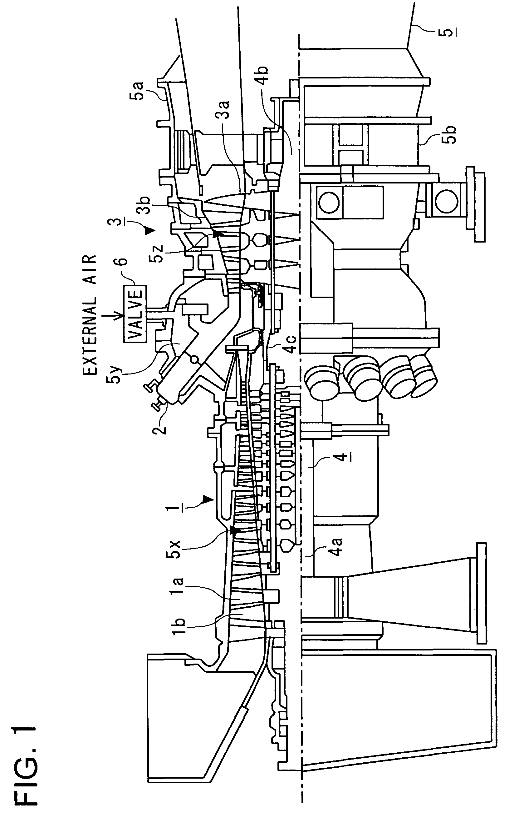
[0052]Referring now to the drawings, a first embodiment of the present invention will be described hereinafter. FIG. 1 is a cross-sectional view showing a construction of a gas turbine in accordance with the present embodiment.

[0053]A gas turbine in FIG. 1 comprises a compressor 1 which compresses the air being sucked from the outside; a combustor 2 which generates combustion gas by being provided with an air compressed by the compressor 1 and a fuel; and a turbine 3 which is rotated by combustion gas being generated in the combustor 2. Then, the gas turbine also comprises a rotor 4 which has rotating blades 1a and 3a provided to the outer circumference thereof; and a casing 5 which has stationary vanes 1b installed alternately with the rotating blades 1a in the axial direction of the rotor 4 and stationary vanes 3b installed alternately with the rotating blades 3a in the axial direction of the rotor 4.

[0054]In addition, the rotor 4 comprises a compressor rotor 4a being provided wit...

second embodiment

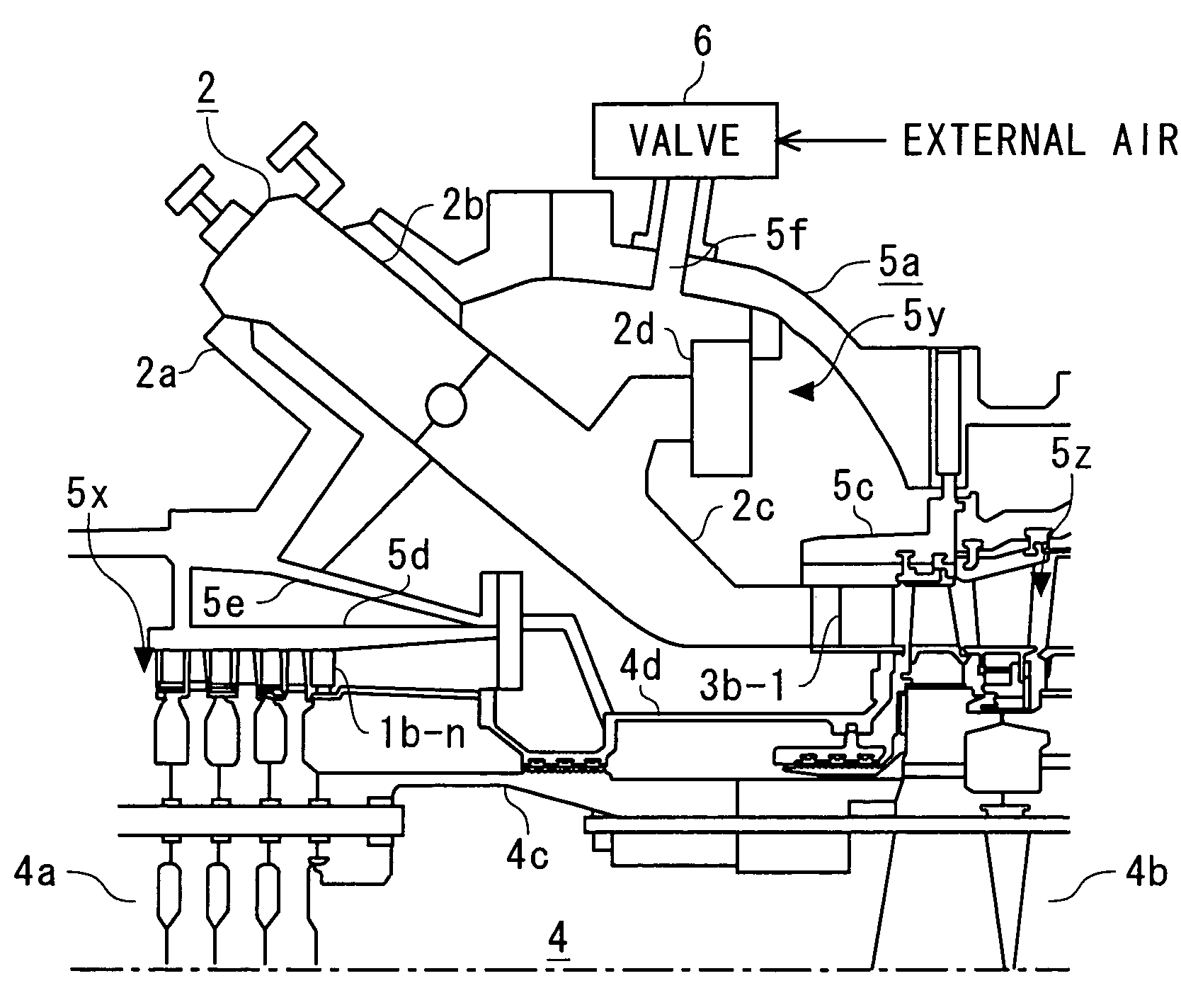
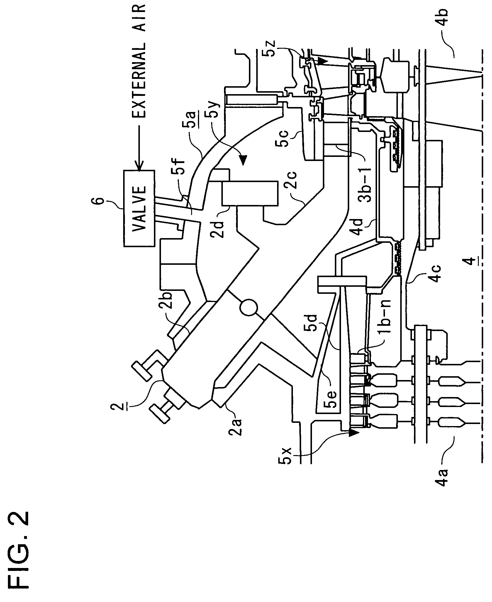
[0063]A second embodiment of the present invention will be described by referring to the drawings. Same as the first embodiment, the gas turbine in accordance with the present embodiment has the gas turbine being constructed as in FIG. 1 serve as the basic construction. The gas turbine in accordance with the present embodiment has a different construction for cooling the upper casing 5a from the first embodiment. Therefore, the constituent portion for cooling the upper casing 5a will be described by referring to FIG. 3. In addition, FIG. 3 is a cross-sectional view showing a construction of the periphery of a combustor casing of a gas turbine in accordance with the present embodiment. In addition, in the construction in FIG. 3, the same portions as the construction in FIG. 2 will be supplied with the same symbols and the detailed description thereof will be omitted.

[0064]As shown in FIG. 3, same as the first embodiment, the gas turbine in accordance with the present embodiment has a...

third embodiment

[0067]A third embodiment of the present invention will be described by referring to the drawings. Same as the first embodiment, the gas turbine in accordance with the present embodiment has the gas turbine being constructed as in FIG. 1 serve as the basic construction. However, the gas turbine in accordance with the present embodiment is different from the first embodiment in the construction for cooling the upper casing 5a. Therefore, constituent portion for cooling the upper casing 5a will be described by referring to FIG. 4. In addition, FIG. 4 is a cross-sectional view showing a construction of the periphery of a combustor casing of a gas turbine in accordance with the present embodiment. In addition, in the construction in FIG. 4, the same portions as the construction in FIG. 2 will be supplied with the same symbols and the detailed description thereof will be omitted.

[0068]As shown in FIG. 4, when the gas turbine in accordance with the present embodiment has a valve 6 connecte...


PUM


Abstract

A valve (6) for supplying the external air to the inside of an upper casing (5a) is provided to the upper casing (5a), and when the operation of a gas turbine is stopped, the external air is introduced from the upper casing (5a) to the inside of the casing (5). When the external air is introduced from the upper casing (5a), the upper casing (5a) is cooled to prevent thermal deformation of the casing (5).

Description

TECHNICAL FIELD[0001]The present invention relates to a casing, which provides an interior thereof with high-temperature ambience and restrains a temperature deviation being caused to each region inside the interior, and also relates to a gas turbine that is provided with such a casing as aforementioned.BACKGROUND ART[0002]In recent years, during the operation of a gas turbine the ambience of a casing interior being covered by the casing becomes high temperature and high pressure. Therefore, when a gas turbine is shut down without taking any actions after the operation, a convective flow is generated inside the casing because the casing interior has a high temperature ambience, and as a result, a temperature deviation occurs inside the casing interior. To be specific, because the high temperature air moves to an upper level area, the upper level area inside the casing interior becomes higher temperature, compared with the lower level area. Due to effects of the temperature deviation...

Claims


Application Information

Patent Timeline
Patent Type & Authority Patents(United States)
IPC IPC(8): F01D25/26
CPCF01D21/00F01D25/08F01D25/24F02C7/18F05D2260/20
Inventor KONDO, MITSURUISHIZAKA, KOICHIIWASAKI, YOSHIFUMI
Owner MITSUBISHI POWER LTD
Why Eureka
Try Eureka