Vane pump using line pressure to directly regulate displacement

a vane pump and line pressure technology, applied in the direction of liquid fuel engines, rotary or oscillating piston engines, rotary piston engines, etc., can solve the problems of pulsations in the output pressure of the pump, disadvantages of the pump taught in bistrow, etc., to reduce the pressure pulsations of the working fluid and reduce the pulsations of the output working fluid

Inactive Publication Date: 2010-09-21
TESMA INT INC
View PDF5 Cites 12 Cited by
  • Summary
  • Abstract
  • Description
  • Claims
  • Application Information

AI Technical Summary

Benefits of technology

[0013]It is an object of the present invention to provide a novel dampened variable displacement vane pump which obviates or mitigates at least one disadvantage of the prior art. It is a further object of the present invention to provide a vane pump with an inlet port with an increased initial cross-sectional flow area.
[0020]The present invention provides a variable displacement vane pump with at least two regulation chambers to provide a regulating force to the cam ring, to counter the force applied to the cam ring by a regulating spring, to reduce pulsations in the output working fluid from the pump. A first one of the chambers is part of the outlet of the pump and is in fluid communication with the outlet port of the pump via a passage, preferably in the form of a groove which allows the pump to be fabricated from a diecast process or the like. A second regulation chamber is connected to the first chamber via an orifice which reduces the pressure pulsations of the working fluid supplied from the first chamber to the second. The configuration and design of pumps in accordance with the present invention allows for flexible packaging for the pump, as the outlet need not overlie the pump outlet.

Problems solved by technology

While variable displacement vane pumps are well known, they do suffer from some disadvantages.
For example, differences in the fluid pressures of the pump chambers (formed between adjacent vanes, the rotor and the cam ring) can cause undesirable variations, or pulsations, on the cam ring, as the pump chambers move with the rotor, which results in pulsations in the output pressure of the pump.
However, the pump taught in Bistrow also suffers from disadvantages.
Specifically, to provide the cored passages required by the Bistrow pump to supply the working fluid to the chamber, the pump must be manufactured by sand casting which increases both the manufacturing cost, production cycle time and precludes the use of desirable materials such as aluminum for forming the body of the pump.
Diecast variable displacement vane pumps with dampening have been produced previously, but such pumps have been limited to having their outlet located underneath and overlying the outlet port of the rotor chamber, to avoid the need for a cored passage and thus permitting the pump to be diecast.
However, because the outlet must be located overlying the rotor chamber outlet port, the layout, port locations, size and volume (i.e. the “packaging”) of such pumps has been quite limited.
Another problem with existing pumps is that the inlet port in the rear plate of prior art pumps is typically in the form of an arc which has a small cross-sectional flow area where it connects to the inlet of the pump and the cross-sectional flow area increases as the arc extends circumferentially about the rotor.
However, such small cross-sectional flow areas can lead to undesired cavitation in the inlet as the pump is operated at higher speeds.

Method used


Image

  • Vane pump using line pressure to directly regulate displacement
  • Vane pump using line pressure to directly regulate displacement
  • Vane pump using line pressure to directly regulate displacement

Examples


Embodiment Construction

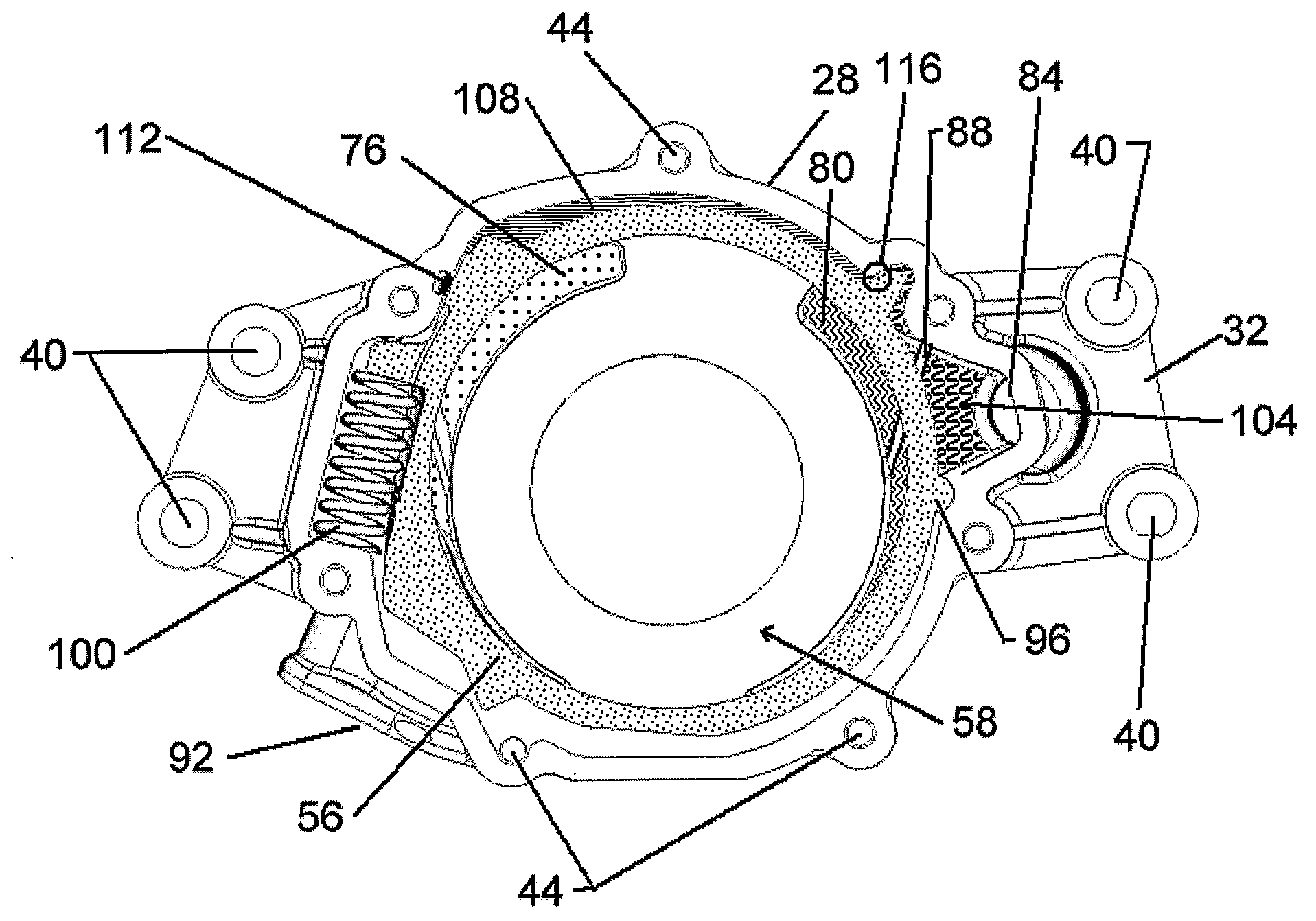
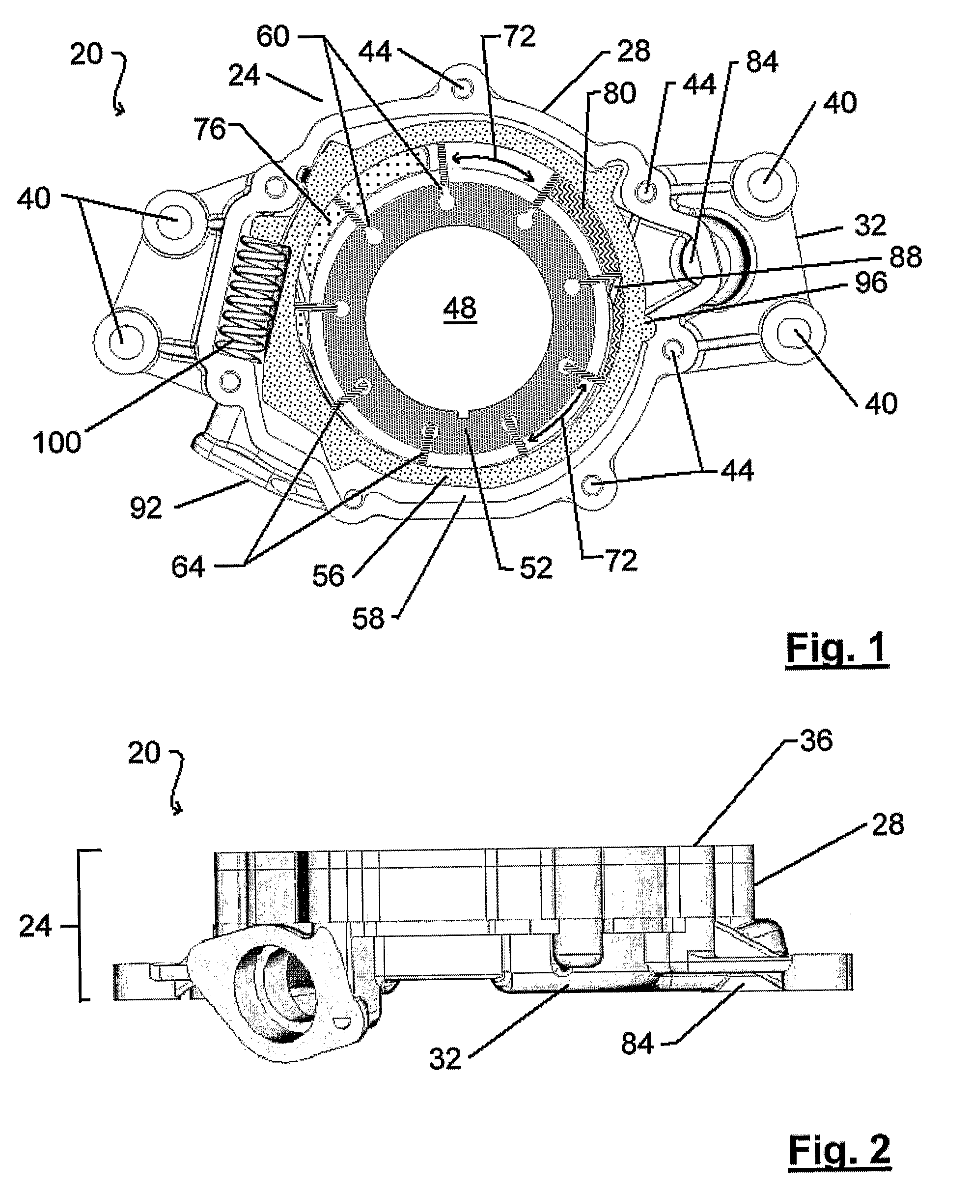
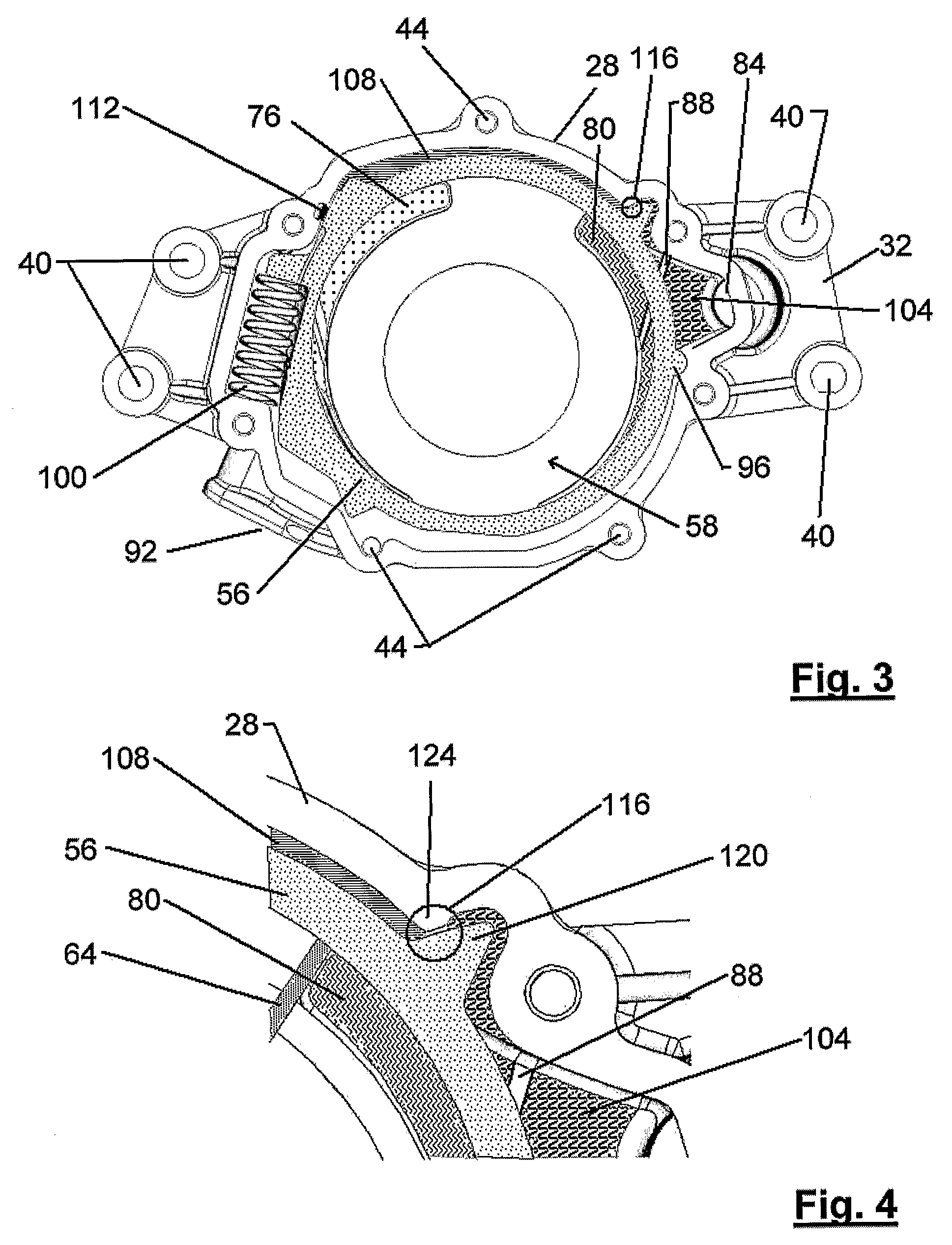
[0035]A variable displacement vane pump in accordance with an embodiment of the present invention is indicated generally at 20 in FIGS. 1 and 2. Pump 20 includes a housing 24 composed of a pump body 28, a rear plate 32 and a cover plate 36 (removed in FIG. 1) placed in spaced-parallel relation to each other. Housing 24 includes one or more holes 40 for mounting onto a mounting plate of an internal combustion engine, or other prime mover, not shown and rear plate 32 includes a set of internally threaded bores which align with through bores 44 in pump body 28 and cover plate 36 to receive bolts to affix cover plate 36, pump body 28 and rear plate 32 to one another. While in the illustrated embodiment pump housing 24 comprises separate components, i.e. pump body 28, rear plate 32 and cover plate 36, it will be apparent to those of skill in the art that pump body 28 can also be integrally formed with either rear plate 32 (in which case housing 24 would comprise a cover plate 36 and an i...


PUM


Abstract

A variable displacement vane pump includes at least two regulation chambers to provide a regulating force to the cam ring to counter the force applied to the cam ring by a regulating spring and reduce pulsation in the output working fluid from the pump. A first regulation chamber is part of the pump outlet and is in fluid communication with the outlet port of the pump via a passage which allows the pump to be fabricated from a diecast process or the like. A second regulation chamber is connected to the first chamber via an orifice which reduces the pressure of working fluid supplied from the first chamber to the second. The pump outlet need not overlie the pump outlet. Further, a pump with an inlet port with a relatively large initial cross-sectional flow area inhibits cavitation of the working fluid when the pump is operated at higher operating speeds.

Description

RELATED APPLICATIONS[0001]This application claims priority from U.S. Provisional Application 60 / 569,055 filed May 7, 2004 and the contents of this U.S. provisional patent application are incorporated herein by reference.FIELD OF THE INVENTION[0002]The present invention relates to variable displacement vane pumps. More specifically, the present invention relates to variable displacement vane pumps in which the cam ring is dampened to deliver output flow with reduced pulsation and / or to variable displacement vane pumps with inlets with increased cross-sectional flow areas.BACKGROUND OF THE INVENTION[0003]Many industrial and automotive devices require a pressurized supply of incompressible fluid such as lubricating oil to operate. Pumps, typically used to supply these fluids, can either be of constant displacement (i.e.—volumetric displacement) or variable displacement designs.[0004]With a constant displacement pump, the pump outputs a substantially fixed volume of working fluid for ea...

Claims


Application Information

Patent Timeline
Patent Type & Authority Patents(United States)
IPC IPC(8): F04C2/00F04C14/18F04C2/344F04C14/22
CPCF04C2/3442F04C14/226F04C15/0049F04C15/06F04C2250/101F04C14/18F04C14/00
Inventor LUTOSLAWSKI, JAREKMUIZELAAR, RICHARD D.
Owner TESMA INT INC
Why Eureka
Try Eureka