Thermal protector

Inactive Publication Date: 2010-09-21
THERMTROL CORP
View PDF30 Cites 20 Cited by
  • Summary
  • Abstract
  • Description
  • Claims
  • Application Information

AI Technical Summary

Benefits of technology

[0016]The self hold thermal protectors of this invention are based upon the discovery that the moving contact utilized therein must have a minimum volume of at least 0.0003 inches3 to attain the desired level of performance. In other words, for the device to be capable of reliable operation for at least 60 cycles of operation (wherein the moving contact is pulled away from the fixed electrical contact by the thermally induced bending caused by heating of the bimetal blade by virtue of an elevated level of current) at a peak amperage of at least 90 amps at 120 volts of alternating current it is necessary for the moving contact to have this minimum volume. In evaluating this performance characteristic the thermal protector will be reset as quickly as possible after it has opened the circuit to subject the thermal protector to the cyc

Problems solved by technology

In vacuum cleaners, overheating of the motor typically results from a blocked or plugged filter, or from one or more objects interfering with the operation of the rotating brush or floor element.
Thus, when the switch is closed, current flows through the PTC resistor, but becau

Method used


Image

  • Thermal protector
  • Thermal protector
  • Thermal protector

Examples


Embodiment Construction

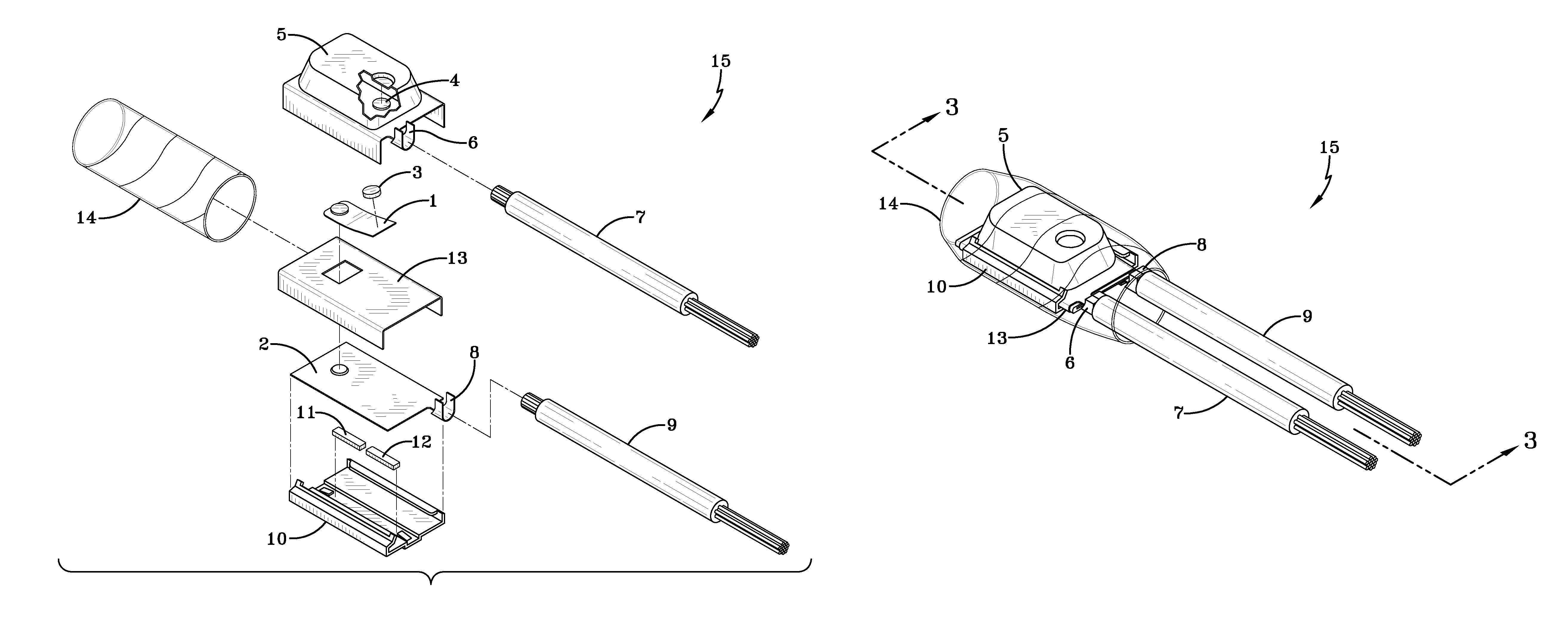
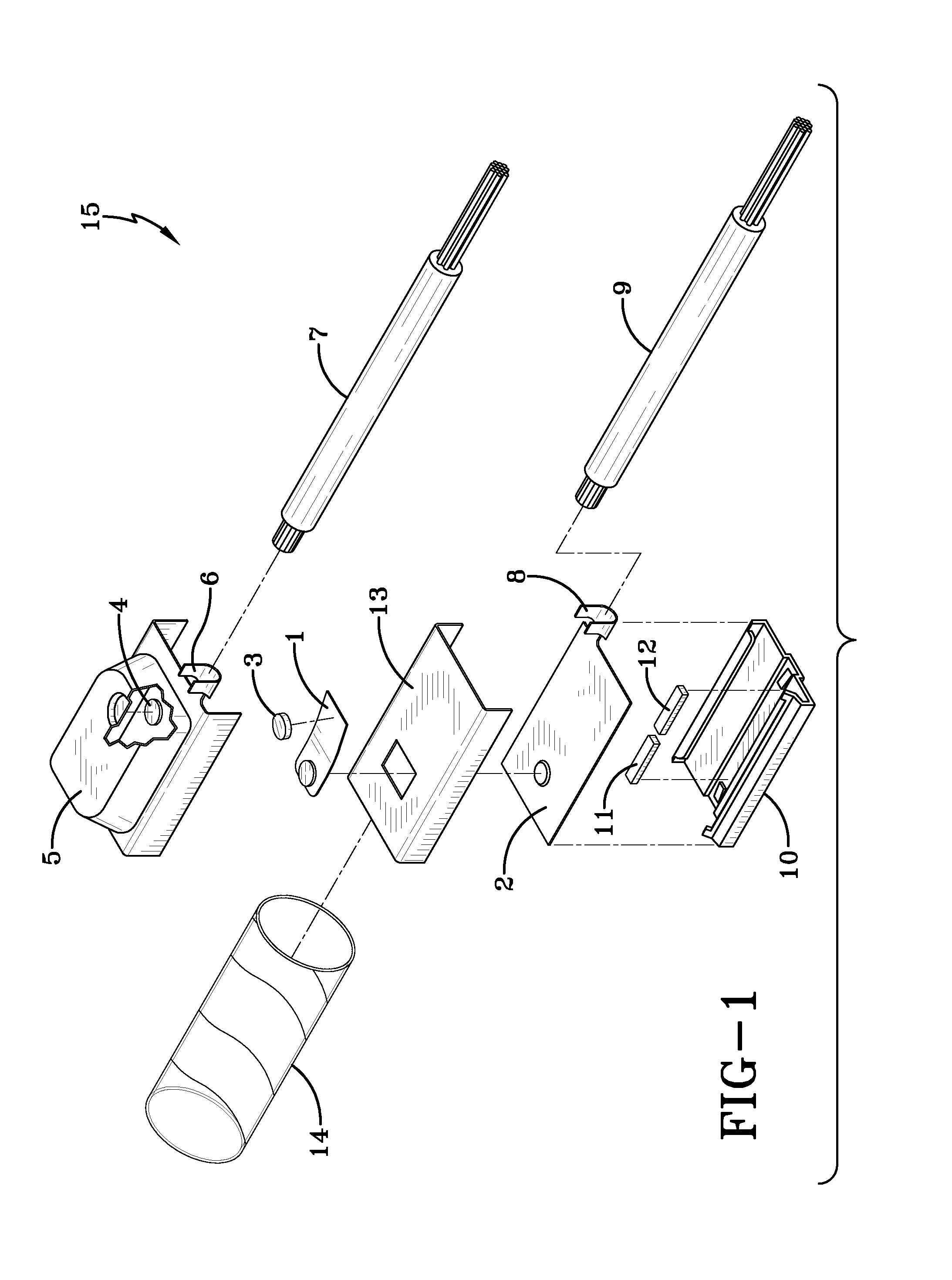
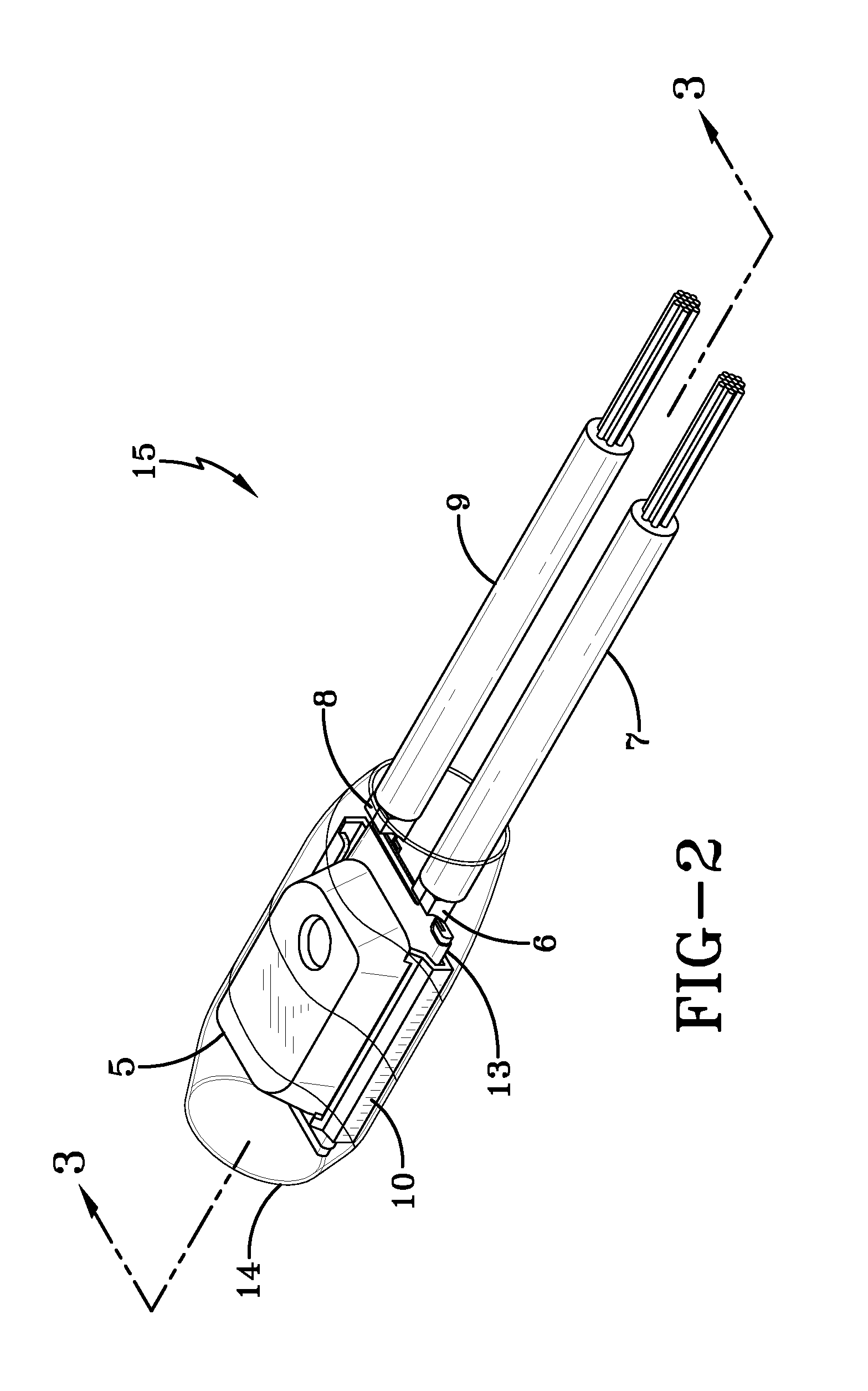
[0044]The self hold thermal protectors of this invention are capable of being used in conjunction with a wide variety of electrical devices. For instance, these thermal protectors can be used to protect electrical devices containing electric motors and electrical transformers from damage caused by abnormal operation which results in an abnormally high temperature or an abnormally high current load. In many cases, the thermal protector will be affixed to the electrical windings of the electric motor to more quickly break the electrical circuit to the motor upon detection of an abnormally high temperature or current. It is desirable to affix the thermal protector to the windings of the electric motor or to a position within close proximity to the electric windings since they are the source of the high heat generated during abnormal operation. Accordingly, the thermal protector will be able to act more quickly in response to abnormal operation in cases where it is positioned near the e...


PUM


Abstract

The present invention relates to a thermal protector which is comprised of a bimetal blade, a moving electrical contact, a fixed electrical contact, and a electrical resistor, wherein the bimetal blade has a fixed end and a moving end, wherein the moving electrical contact is positional toward the moving end of the bimetal blade, wherein the moving electrical contact has a minimum volume of 0.0003 in3, wherein electrical resistor generates sufficient heat to keep the bimetal blade above a reset temperature and to maintain the bimetal blade in a bent position wherein the moving electrical contact remains away from the fixed electrical contact during periods of continued application of the electrical current, wherein the reset temperature is above ambient temperature, and wherein the thermal protector is capable of at least 60 cycles of operation at a peak amperage of at least 90 amps at 120 volts of alternating current.

Description

[0001]This application claims the benefit of the priority of U.S. Provisional Patent Application Ser. No. 60 / 919,123 filed on Mar. 20, 2007. The teachings of U.S. Provisional Patent Application Ser. No. 60 / 919,123 are incorporated herein by reference in their entirety.BACKGROUND OF THE INVENTION[0002]It is desirable for electrical devices, particularly electrical devices that include an electric motor, to be equipped with a thermal protector that will stop operation of the device in the event that the operating temperature of the device exceeds a predetermined maximum operating temperature. Stopping the device is desirable because it can prevent mechanical damage from occurring and frequently can prevent an electrical motor from operating at unacceptably high temperatures. A number of devices that perform this general function are know in the prior art.[0003]U.S. Pat. No. 6,553,611 discloses a thermal protector device for utilization in conjunction with vacuum cleaners. In vacuum cl...

Claims


Application Information

Patent Timeline
IPC IPC(8): H01H37/52H01H37/14
CPCH01H37/5436
Inventor KOMER, JOHN M.
Owner THERMTROL CORP
Why Eureka
Try Eureka