

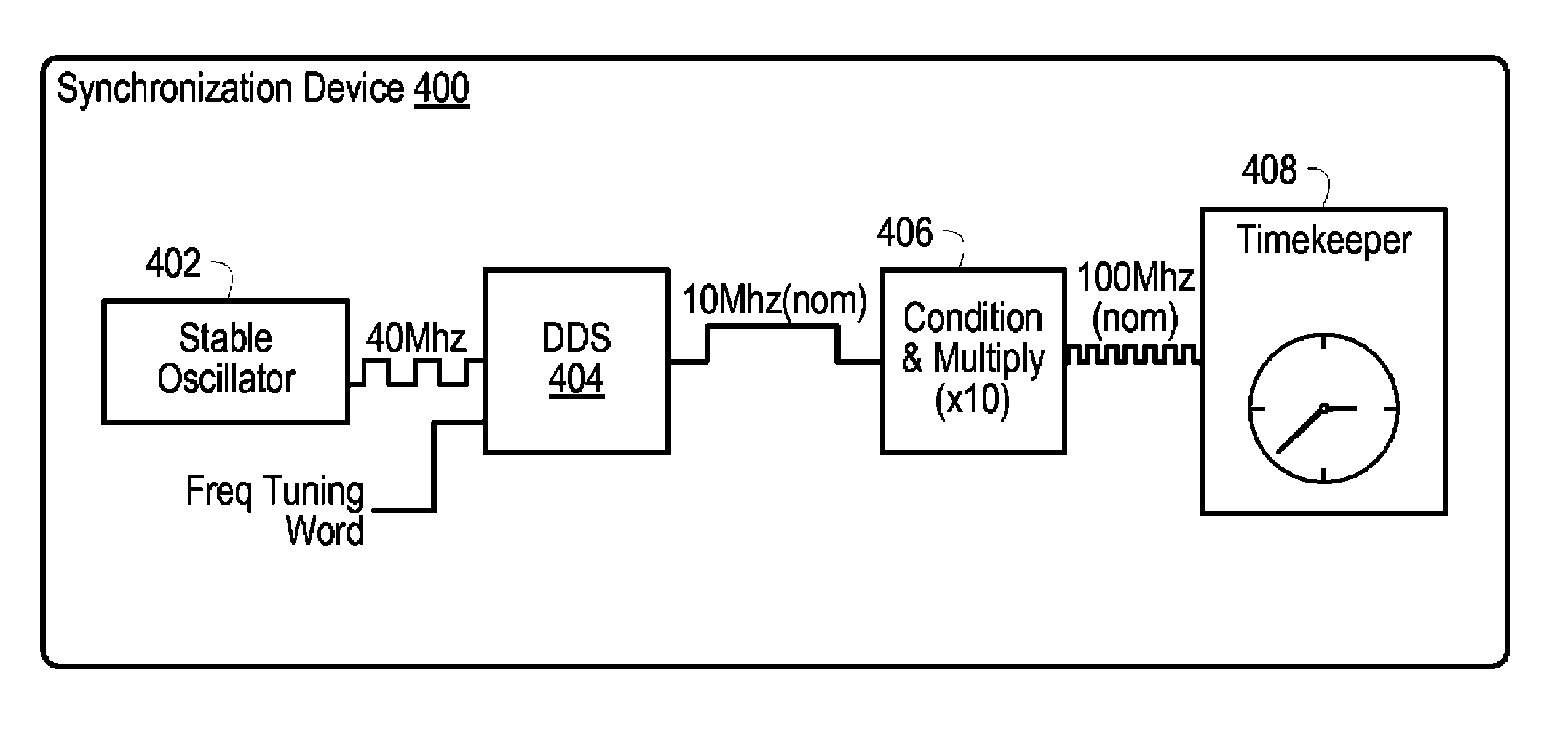
Aligning timebases to share synchronized periodic signals
a timebase and periodic signal technology, applied in the direction of digital transmission, multiplex communication, instruments, etc., can solve the problem of no longer agreeing on the edge, achieve the effect of facilitating the resolution of the edge of the reference signal, superior results, and facilitate multiple devices
- Summary
- Abstract
- Description
- Claims
- Application Information
AI Technical Summary
Benefits of technology
Problems solved by technology
Method used
Image

Examples
Embodiment Construction
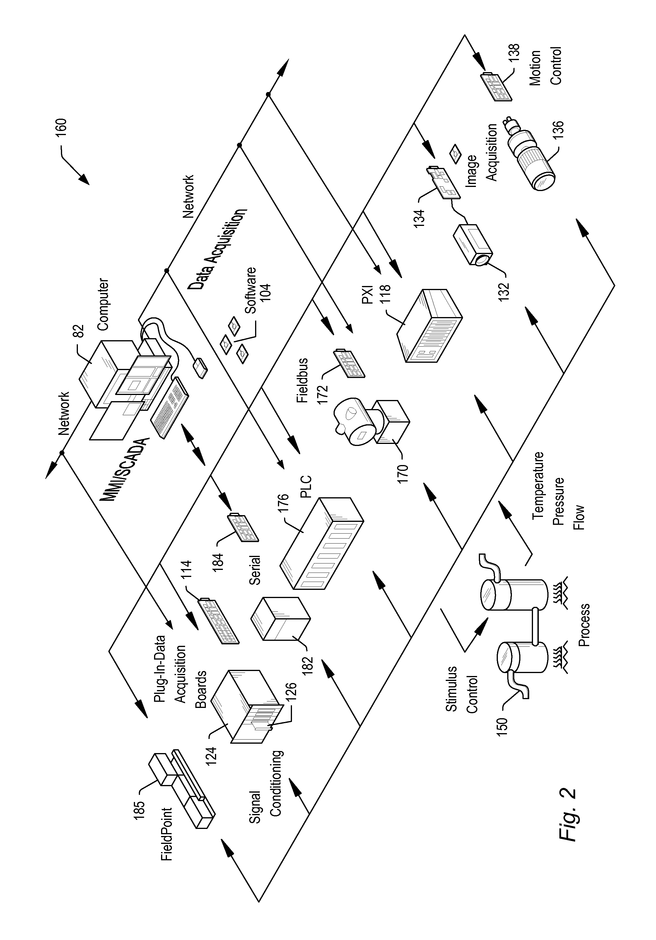
[0028]Embodiments of the present invention may be used in systems configured to perform test and / or measurement functions, to control and / or model instrumentation or industrial automation hardware, or to model and simulate functions, e.g., modeling or simulating a device or product being developed or tested, etc. However, it is noted that the present invention may equally be used for a variety of applications, and is not limited to the applications enumerated above. In other words, applications discussed in the present description are exemplary only, and the present invention may be used in any of various types of systems. Thus, the system and method of the present invention is operable to be used in any of various types of applications, including the control of other types of devices such as multimedia devices, video devices, audio devices, telephony devices, Internet devices, etc.
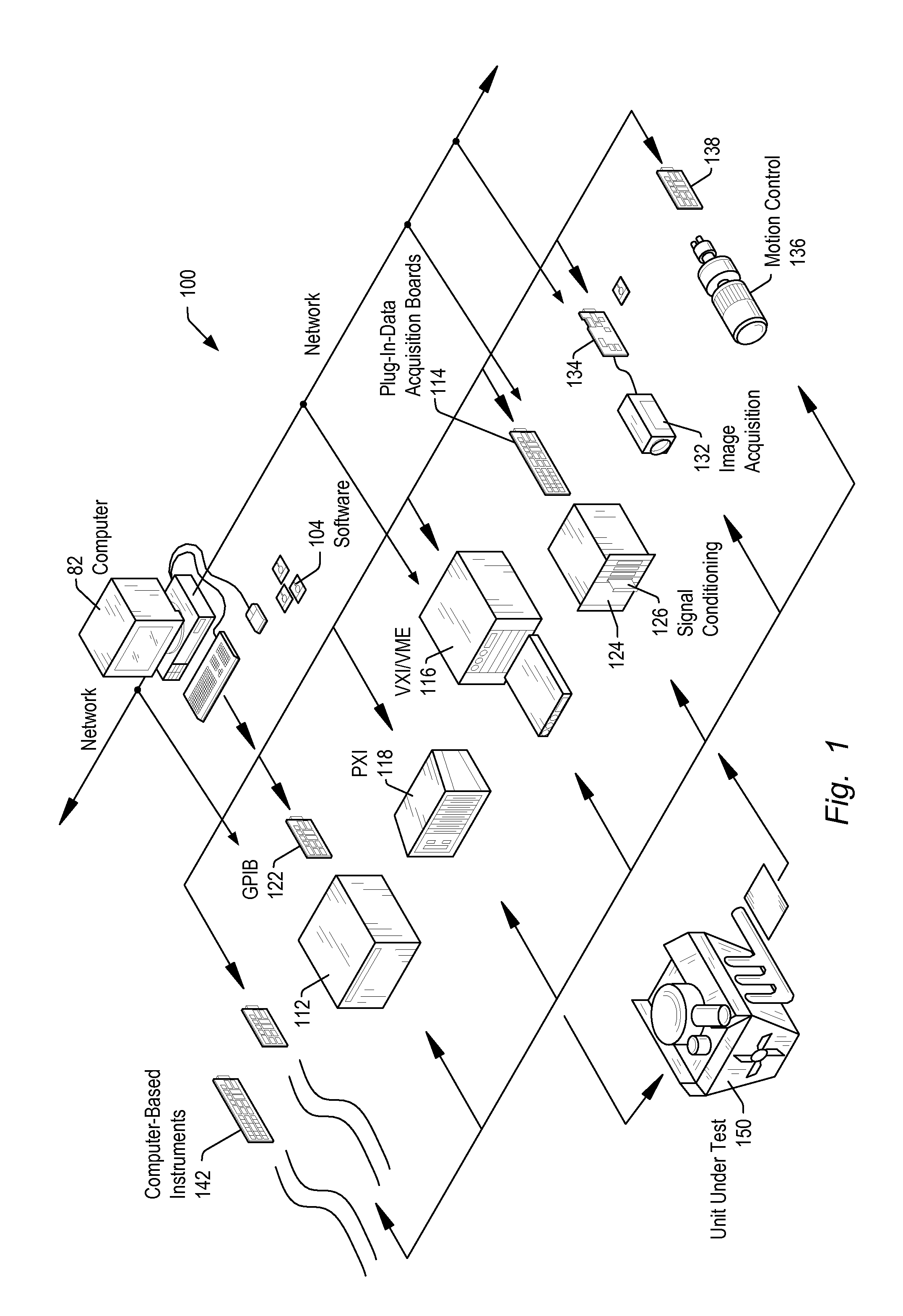
[0029]FIG. 1 illustrates an exemplary instrumentation control system 100 which may be configured accor...
PUM
 Abstract
Description
Claims
Application Information