Adaptive multi-axis sensor array

a multi-axis sensor and array technology, applied in the field of position determining hardware, can solve the problems of significant limitations of existing position detecting systems such as satellite based systems including gps, vor, cell tower signals, other microwave signals, and the creation of significant distortion in accurate positioning determination, so as to achieve the effect of extreme robustness and reliabl

a multi-axis sensor and array technology, applied in the field of position determining hardware, can solve the problems of significant limitations of existing position detecting systems such as satellite based systems including gps, vor, cell tower signals, other microwave signals, and the creation of significant distortion in accurate positioning determination, so as to achieve the effect of extreme robustness and reliabl

US20080319707A1Inactive Publication Date: 2008-12-25ALLAN SPACE TIME SOLUTIONS

Image

  • Adaptive multi-axis sensor array
  • Adaptive multi-axis sensor array
  • Adaptive multi-axis sensor array

Examples


Embodiment Construction

)

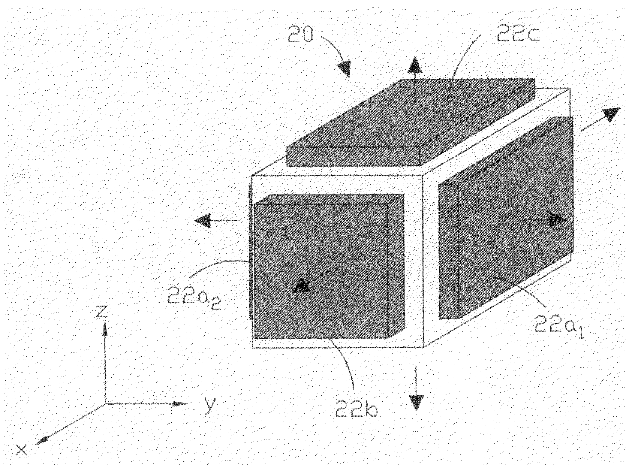
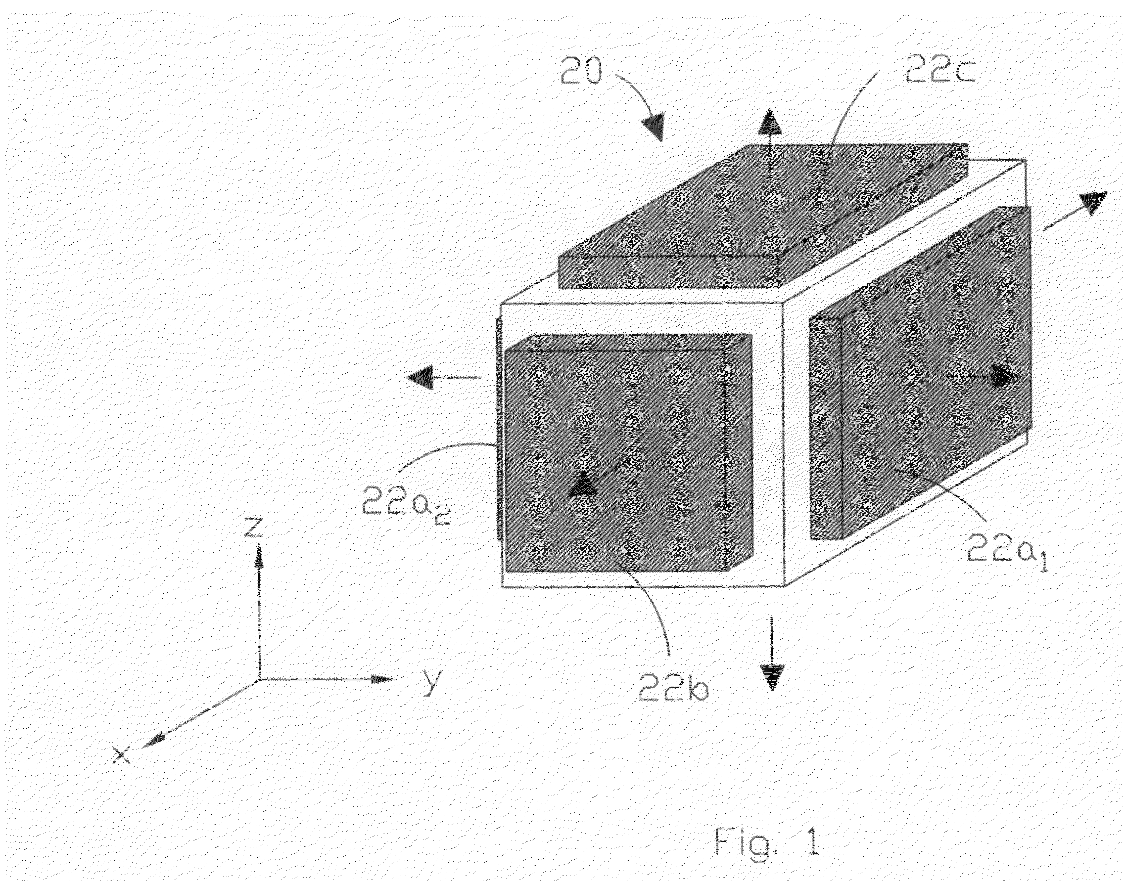
[0037]A schematic depiction of a first embodiment of the adaptive multi-axis sensor array or ensemble of the present invention is depicted in FIG. 1 generally at 20. As shown in FIG. 1, the multi-axis sensor array comprises 3 pairs of opposed piezoelectric oscillators 22. By way of example, oscillators 22a1, 22a2 have primary axes extending in opposite directions along, for example, the y-axis, while oscillators 22b extend along the x-axis and 22c extend in opposite directions along the z-axis. While sensor array 20 is configured to permit data to be gathered regarding all 3 orthogonal longitudinal axes and, by virtue of the paired oscillators 22, all three rotational axes as well, it is envisioned that other applications may only require data gathering to one or two of the principle axes. Accordingly, the invention is directed to a plurality of 2 n piezoelectric oscillators, where n is the number of axes of interest, each piezoelectric oscillator of the plurality of 2 n being one ...


PUM


Abstract

A sensor array made up of 2 n piezoelectric oscillators (preferably paired quartz oscillators) is provided in which n equals the number of axes of interest and each one of the pairs of oscillators has a principle axis directed oppositely from the other of its pair. A controller which preferably includes a microprocessor, makes use of the dynamic relationships of the sensors in the array to adaptively assess the magnitude of weighting factors needed to correct the output signal from each oscillator for environmental and systematic effects to provide optimum frequency and phase output for computing position, velocity, and acceleration. Preferably, a seventh reference oscillator is provided in the center of the array which is canted relative to each of the three orthogonal axes by 45°. This adaptive sensor array is capable of determining position within one meter along any of the x, y, and z axes without the need for any external (e.g., GPS) signal. In addition, unlike other sensor systems, it is capable of providing local vertical on a continuous basis. The array can also determine if an object is moving in any translational or rotational direction, within the measurement capabilities of the system.

Description

BACKGROUND AND SUMMARY OF THE INVENTION[0001]The present invention is directed to position determining hardware. More particularly the present invention is directed to an adaptive multi-axis sensor array known as Ensemble of Quartz Clocks Adapting To the Environment (EQUATE).[0002]Systems capable of providing position, acceleration and velocity data are well known in the prior art. The more common ones utilize signals provided by a Global Position System (GPS) which are fed to an interface with a navigation computer to provide position, velocity and time reference signals. Other systems employ microwave signals to provide a localized solution as for an airport. Radio transmitters are used in certain applications to triangulate to provide independent navigation data.[0003]Existing position detecting systems such as satellite based systems including GPS, VOR, cell tower signals, other microwave signals, have significant limitations. Although these systems provide useful information fo...

Claims


Application Information

Patent Timeline
25 Dec 2008
Publication
US20080319707A1
IPC
G01C21/00
CPC
G01C21/165; G01C21/183
Inventors
ALLAN, DAVID W.; KUSTERS, JOHN A