Cavity back golf club head

a golf club head and cavity technology, applied in golf clubs, golf, sport apparatus, etc., can solve the problems of excessive vibration, difficulty in hitting the average golfer, and the club may become difficult for the average golfer to properly swing, so as to reduce the amount of “peeling” and reduce the shrinkage

Inactive Publication Date: 2010-09-28
COBRA GOLF
View PDF21 Cites 83 Cited by
  • Summary
  • Abstract
  • Description
  • Claims
  • Application Information

AI Technical Summary

Benefits of technology

[0006]The invention includes a cavity of a golf iron club head that is substantially filled with dual durometer silicone material. This design accomplishes several things. First, it allows the head to have a larger volume for a given amount of weight, in that the silicone material adds very little weight to the iron club head relative to the volume added. Secondly, it provides for attaching a polycarbonate insert to the silicone. And thirdly, it creates a method for efficiently dampening undesirable vibrations.
[0009]The first silicone is attached to the interior wall by an adhesive that is brushed on the surface. However, an important design concept is the omission of adhesive on the interior surface around area where the sole and bottom face are formed. This allows the relatively hard first silicone to shrink and expand in the no-adhesive zone rather than on the exposed side where the softer second silicone is placed. This reduction of shrinkage at the outer part of the first silicone reduces the amount of “peeling” between the two silicones, which happens when the material pulls away from the walls.

Problems solved by technology

Therefore, the club heads of the long irons have a smaller strike face surface area than the short irons and are typically more difficult for the average golfer to hit consistently well.
For example, if the club head of a three iron is increased in size and weight, the club may become difficult for the average golfer to properly swing.
Another problem area for the average golfer is that of excess vibration resulting from an off center impact with the golf ball.
In addition to inaccuracy of the shot, vibrations are indicative of a less than ideal transfer of energy from the club to the ball, and consequently represent inefficiency in the club head.

Method used


Image

  • Cavity back golf club head
  • Cavity back golf club head
  • Cavity back golf club head

Examples


Embodiment Construction

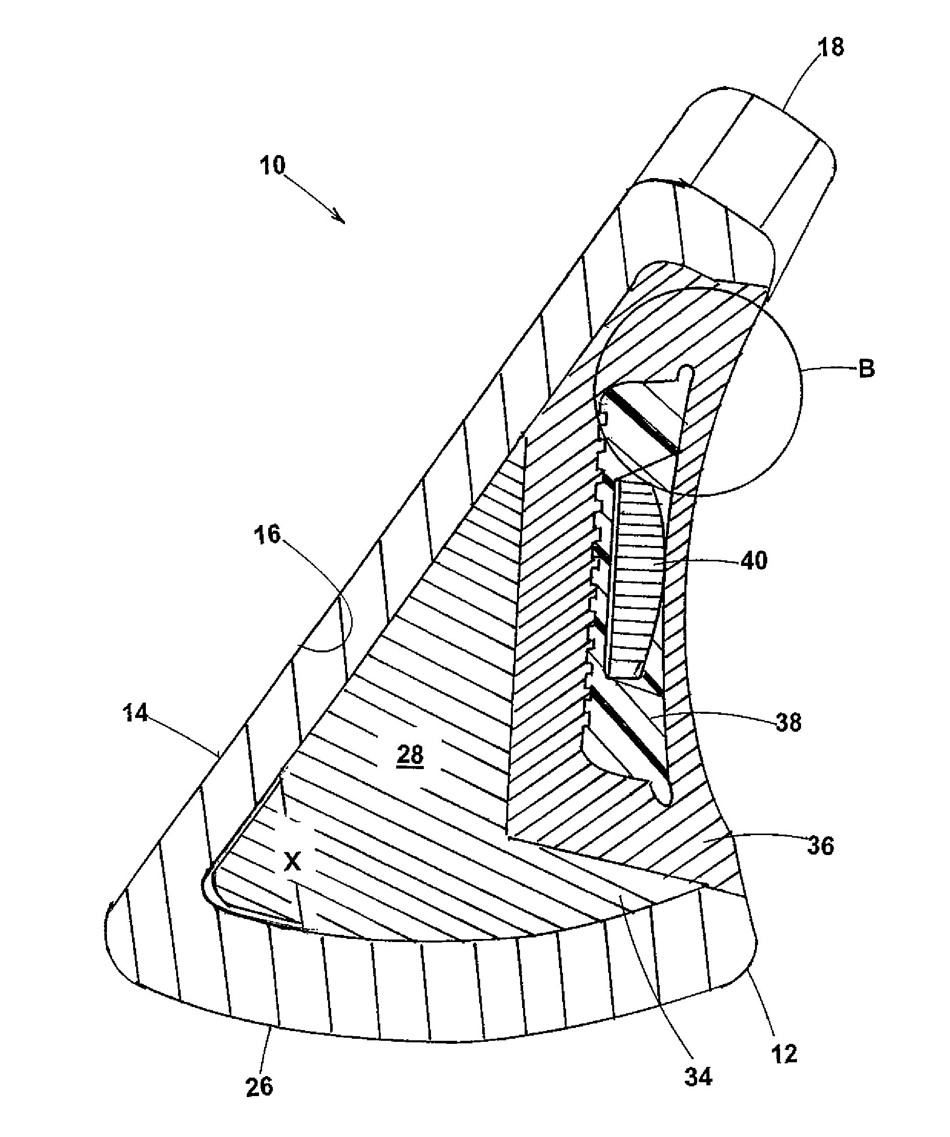
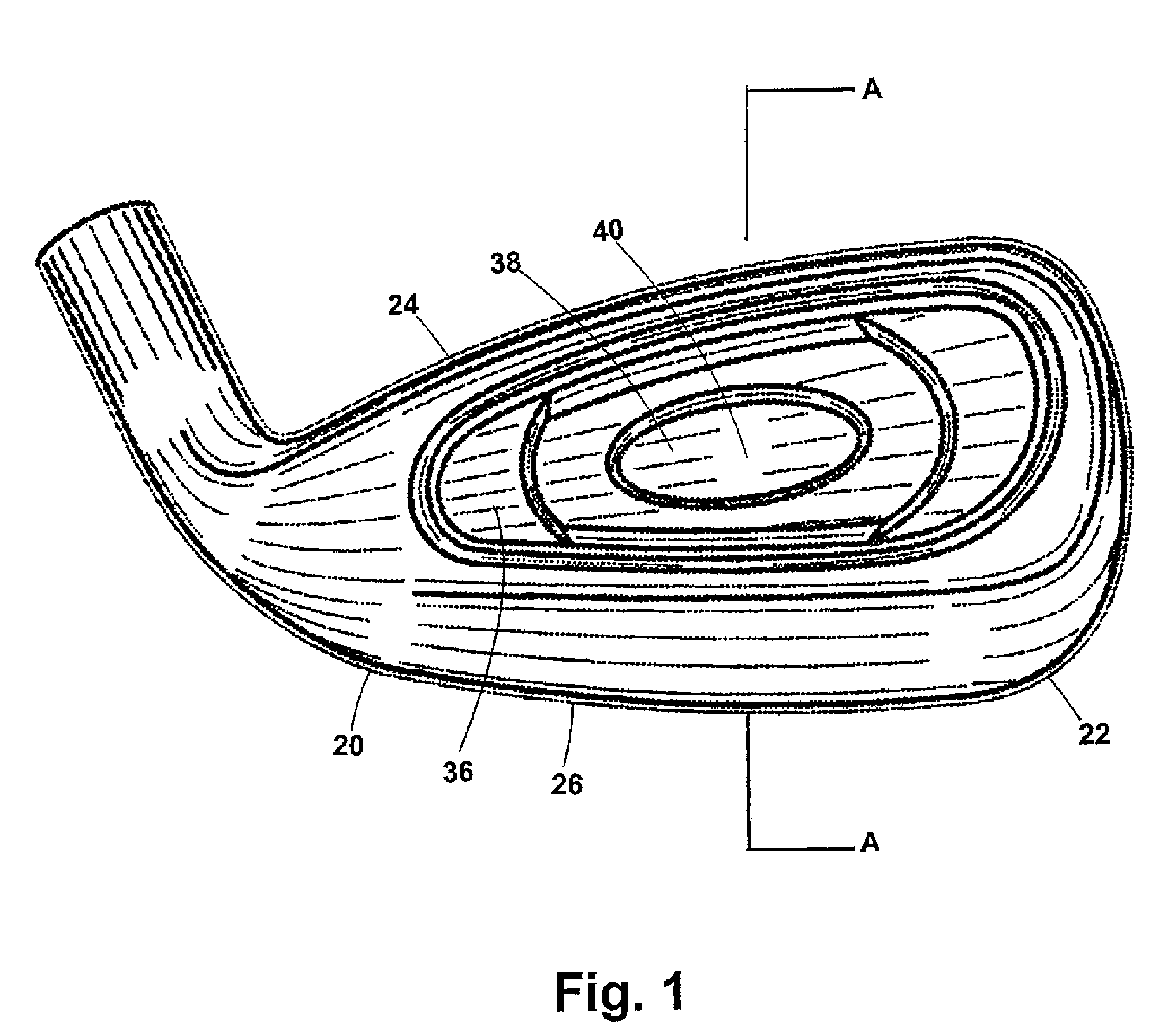
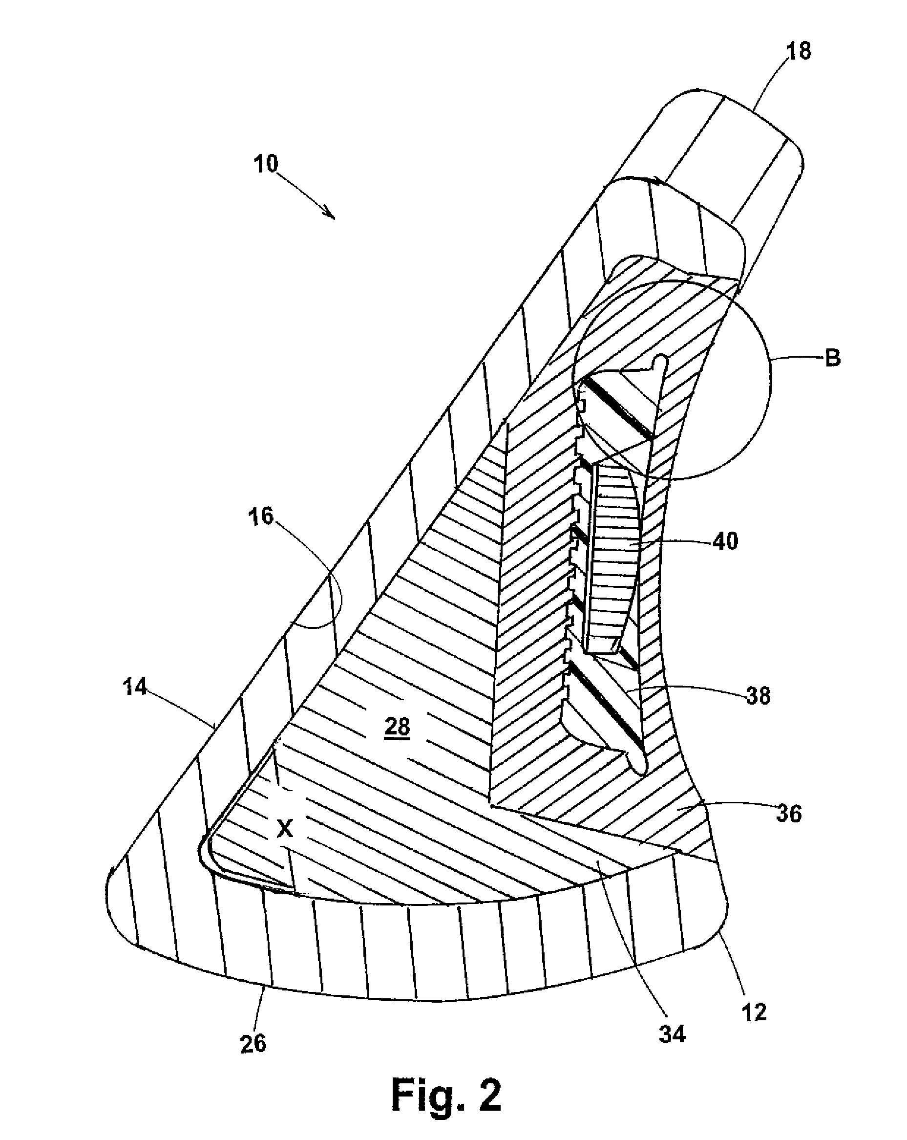
[0012]Referring to FIGS. 1-2, golf club head 10 is constructed in accordance with a preferred embodiment of this invention. It includes a cavity back body 12, preferably cast, having a front face 14, interior surface 16, a hosel portion 18, a heel portion 20, a toe portion 22, an upper edge 24 and lower edge 26. The body 12 includes a cavity 28 that is defined by the interior surface 16.

[0013]In the preferred embodiment, the cavity 28 is preferably formed in the body 12 during the casting process, but may also be formed subsequently by machining. Cavity 28 is substantially filled with a hot molded silicone. The hot molded silicone is disposed into the cavity 28 in two separate shots. The first shot is of a precise pre-cut amount of relatively hard hot molded silicone 34, which when disposed is contiguous to a substantial portion of the interior surface 16 of the body 12. The first silicone has a Shore A hardness between about 70 to 80, preferably 80, which in addition to shrinking l...


PUM


Abstract

A golf club head having a cavity back design with a cavity therein for placement of lightweight dual-durometer silicone. The club head is prepared by brushing an adhesive onto the interior wall, but omitting a pre-selected area of the wall to allow silicone to shrink away at the omitted area to allow for control of the shrinkage. A first shot of 80 Shore A silicone is placed into the cavity and disposed against the interior wall. Next, a softer 50 Shore A silicone is juxtaposed against the first shot of silicone and it is pressed using a hot mold finishing tool wherein a substantial portion of the cavity is filled. A polycarbonate insert is attached to an outer surface of the second silicone to provide a zero gap appearance. A tan delta ratio of the first silicone to the second silicone is greater than 1.6. A storage modulus of the first silicone is at least three times greater than the second silicone. And, a loss modulus of the first silicone is at least ten times the second silicone.

Description

FIELD OF THE INVENTION[0001]The present invention generally relates to golf clubs and, more particularly to cavity back irons filled with hot molded dual durometer silicone for use as a damping material.BACKGROUND OF THE INVENTION[0002]The individual golf club heads in a set typically increase progressively in strike face surface area and weight as the clubs progress from the long irons to the short irons. Therefore, the club heads of the long irons have a smaller strike face surface area than the short irons and are typically more difficult for the average golfer to hit consistently well. For conventional club heads, this arises at least in part due to the smaller sweet spot of the corresponding smaller strike face.[0003]To help the average golfer consistently hit the sweet spot of a club head, many golf clubs are available having heads with so-called cavity back designs with increased perimeter weighting. Another more recent trend has been to simply increase the overall size of th...

Claims


Application Information

Patent Timeline
Patent Type & Authority Patents(United States)
IPC IPC(8): A63B53/00
CPCA63B53/04A63B53/047A63B53/0475A63B59/0092A63B2053/0408A63B2053/0412A63B2209/00A63B60/54A63B53/0412A63B53/0408A63B60/00
Inventor CLAUSEN, KARL A.LO, RYANMORRIS, THOMAS C.
Owner COBRA GOLF
Why Eureka
Try Eureka