Intravascular stents

a technology of endoprosthesis and stent, which is applied in the field of expandable endoprosthesis devices, can solve the problems of lack of both the low profile and extreme flexibility needed, and the size of the body lumen can be quite small, and achieves the effects of improving facilitating delivery, and enhancing the strength of the end of the stent and the overall radiopacity of the sten

Inactive Publication Date: 2010-09-28
ABBOTT CARDIOVASCULAR
View PDF17 Cites 7 Cited by
  • Summary
  • Abstract
  • Description
  • Claims
  • Application Information

AI Technical Summary

Benefits of technology

[0014]The stents of the present invention also have strut patterns which enhance the strength of the ends of the stent and the overall radiopacity of the stent, yet retain high longitudinal flexibility along their longitudinal axis to facilitate delivery through tortuous body lumens and remain stable when expanded radially to maintain the patency of the body lumen.
[0015]The resulting stent structures are a series of radially expandable cylindrical elements that are spaced longitudinally close enough so that small dissections in the wall of a body lumen may be pressed back into position against the luminal wall, but not so close as to compromise the longitudinal flexibility of the stent both when negotiating through the body lumens in their unexpanded state and when expanded into position within the vessel. The design of the stents contribute to form small gaps between struts to minimize tissue prolapse. Each of the individual cylindrical elements may rotate slightly relative to their adjacent cylindrical elements without significant deformation, cumulatively providing stents which are flexible along their length and about their longitudinal axis, but which still are very stable in their radial direction in order to resist collapse after expansion.
[0016]In one embodiment of the present invention, each cylindrical element of the stent includes six peak portions (often referred to as “crowns”) and six valley portions which provide sufficient coverage of the vessel when placed in the expanded or deployed position. In this design, each cylindrical element consists of an alternating pattern of valley portions, including double-curved (W) portions and Y-shaped portions, and peak portions, including alternating, inverted double-curved portions and Y-shaped portions. The plurality of interconnecting members extend between adjacent cylindrical elements and connect adjacent cylindrical elements to one another. In particular, interconnecting members are connected both axially and circumferentially to three alternating double-curved portions to connect a cylindrical element to three Y-shaped portions of an adjacent cylindrical element, and interconnecting members are connected both axially and circumferentially to three alternating, inverted double-curved portions to connect a cylindrical element to three alternating, inverted Y-shaped portions of an adjacent cylindrical element. This particular alignment of interconnecting members provides adequate flexibility to the stent and also helps prevent foreshortening of the stent as it expands radially outward. In addition, the particular placement of the interconnecting links within the valley portions of each double-curved portion is designed to increase axial stiffness and help reduce the protrusion of the Y-shaped portions from the circumference of the stent. Further, the discontinuing pattern of interconnecting members results in a highly flexible stent that does not kink upon bending. Both the distal and proximal ends of this stent design can be entirely composed of “W” patterns which provide additional strength to the ends of the stent. The resulting stent provides sufficient coverage for vessel scaffolding while maintaining excellent flexibility to reach distal lesions and possessing sufficient radial strength to hold the target vessel open. An alternative pattern using eight crowns and eight discontinuous interconnecting members also can be utilized and will exhibit these same physical properties.
[0017]The serpentine pattern of the individual cylindrical elements are in phase with each other in order to reduce the contraction of the stent along their length when expanded. In these embodiments of the present invention, interconnecting members align behind each other in an alternating fashion to create a discontinuous “spine” which extends from one end of the stent to the other. Specifically, alternating rows of interconnecting members are preferably used to connect adjacent cylindrical elements, with the exception, however, at end of the stent wherein at least two continuous rows of interconnecting members form one continuous spine. This particular construction also helps prevent the stent from foreshortening when expanded.

Problems solved by technology

One of the difficulties encountered in using prior art stents involve maintaining the radial rigidity needed to hold open a body lumen while at the same time maintaining the longitudinal flexibility of the stent to facilitate its delivery and accommodate the often tortuous path of the body lumen.
In many procedures which utilize stents to maintain the patency of the patient's body lumen, the size of the body lumen can be quite small which prevents the use of some commercial stents which have profiles which are entirely too large to reach the small vessel.
Since many commercial stents lack both the low profile and extreme flexibility needed to reach such distal lesions, they are not available for utilization for such procedures.

Method used


Image

  • Intravascular stents
  • Intravascular stents
  • Intravascular stents

Examples


Embodiment Construction

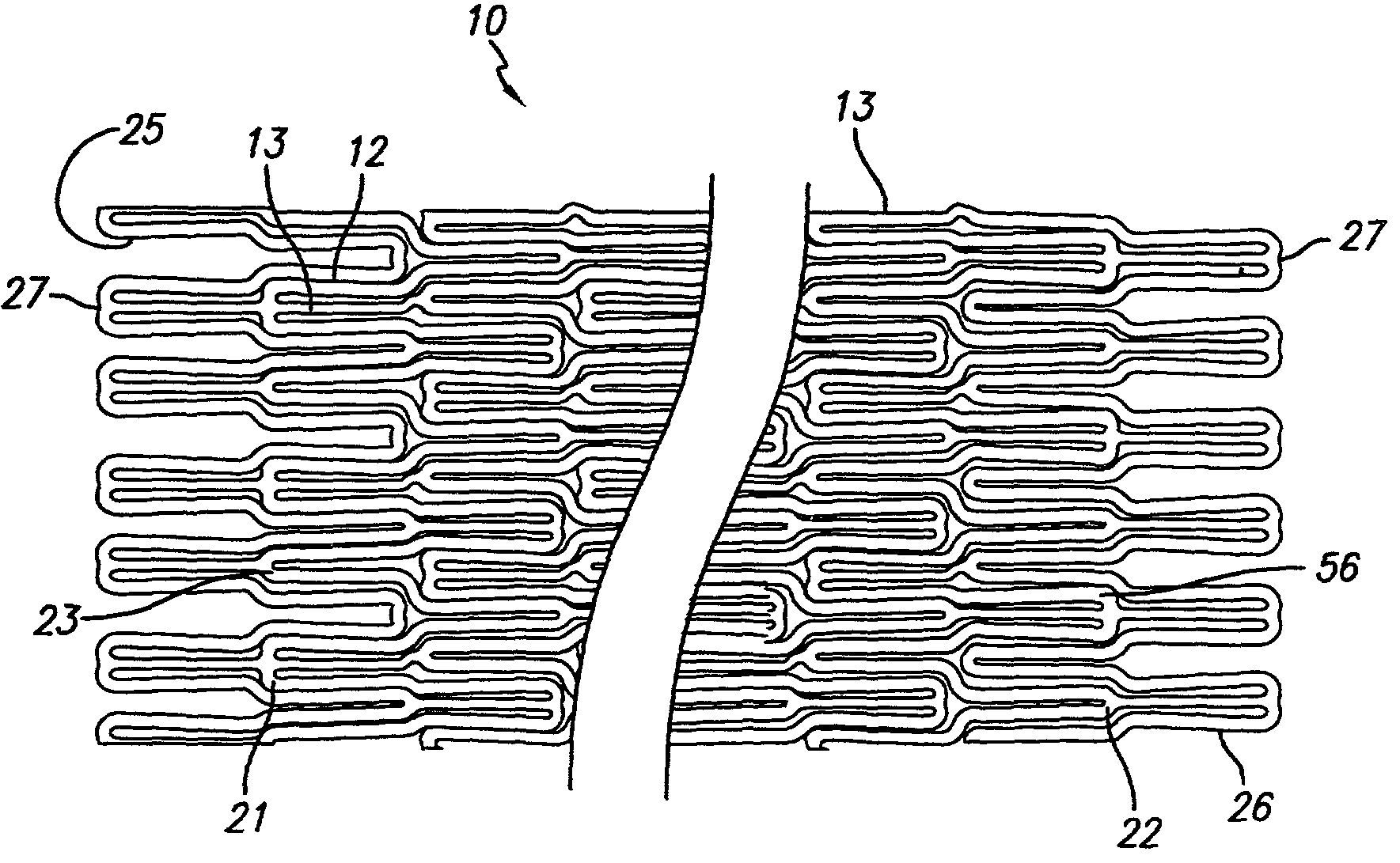
[0036]Prior art stent designs, such as the MultiLink Stent™ manufactured by Advanced Cardiovascular Systems, Inc., Santa Clara, Calif., include a plurality of cylindrical rings that are connected by three connecting members between adjacent cylindrical rings. Each of the cylindrical rings is formed of a repeating pattern of U-, Y-, and W-shaped members, typically having three repeating patterns forming each cylindrical element or ring. A more detailed discussion of the configuration of the MultiLink Stent™ can be found in U.S. Pat. No. 5,569,295 (Lam) and U.S. Pat. No. 5,514,154 (Lau et al.).

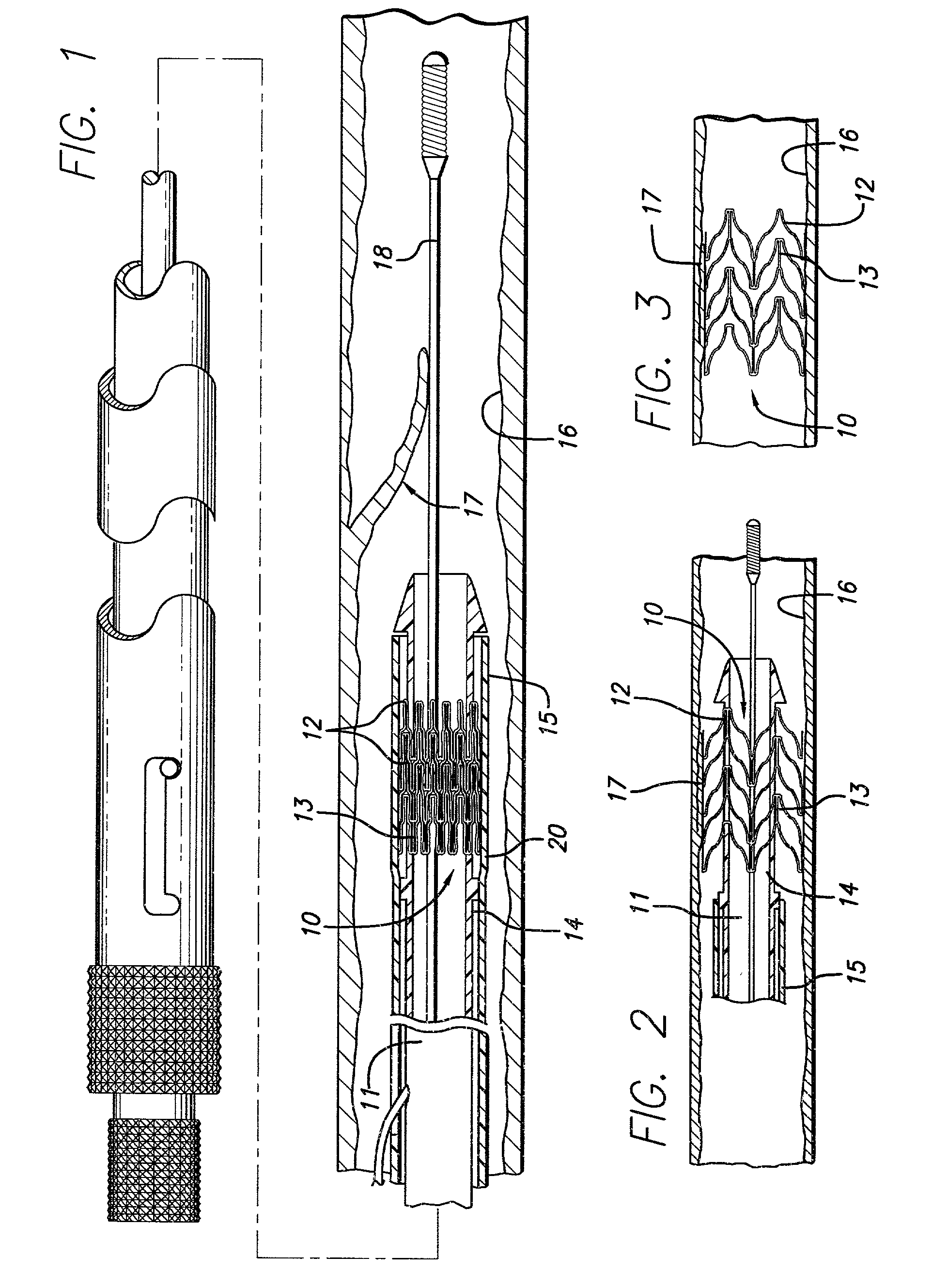
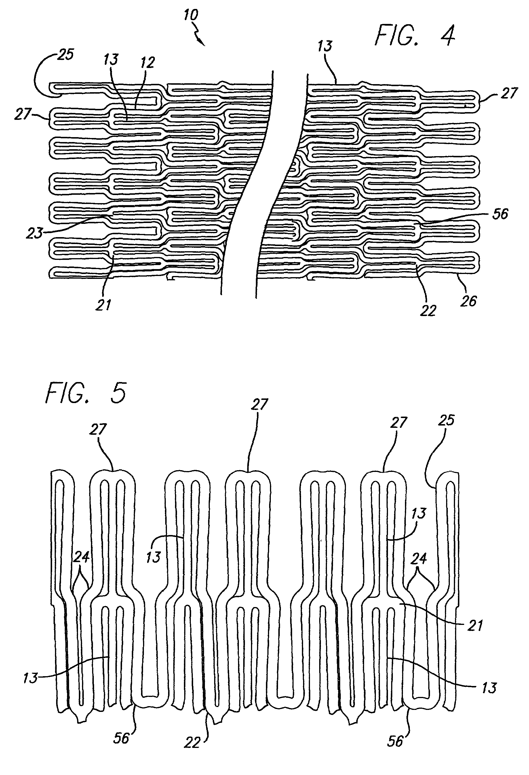
[0037]Beyond those prior art stents, FIG. 1 illustrates an exemplary embodiment of stent 10 incorporating features of the present invention, which stent is mounted onto delivery catheter 11. FIG. 4 is a plan view of this exemplary embodiment stent 10 with the structure flattened out into two dimensions to facilitate explanation. Stent 10 generally comprises a plurality of radially expandable cyl...


PUM

PropertyMeasurementUnit
diametersaaaaaaaaaa
ultimate tensile strengthaaaaaaaaaa

Abstract

Stent designs for use in vessels, such as the carotid and coronary arteries, are disclosed. The stents consist of a plurality of radially expandable cylindrical elements generally aligned on a common longitudinal stent axis and interconnected by one or more interconnecting members placed so that the stent is flexible in a longitudinal direction. The cylindrical elements form a generally serpentine wave pattern transverse to the longitudinal axis between alternating valley portions and peak portions. The interconnecting members are attached to the double-curved portions to connect a cylindrical element to an adjacent cylindrical element and interconnecting members are attached to the inverted double-curved portions to connect the cylindrical element to the other adjacent cylindrical element. The stent designs include both a six crown and an eight crown stent which exhibit flexibility and sufficient radial strength to support the vessel.

Description

BACKGROUND OF THE INVENTION[0001]The present invention relates to expandable endoprosthesis devices, generally called stents, which are adapted to be implanted into a patient's body lumen, such as a blood vessel, to maintain the patency thereof. Stents are particularly useful in the treatment and repair of blood vessels after a stenosis has been compressed by percutaneous transluminal coronary angioplasty (PTCA), percutaneous transluminal angioplasty (PTA), or removed by atherectomy or other means, to help improve the results of the procedure and reduce the possibility of restenosis.[0002]Stents are generally cylindrically-shaped devices which function to hold open and sometimes expand a segment of a blood vessel or other arterial lumen, such as coronary artery. Stents are usually delivered in a compressed condition to the target site and then deployed at that location into an expanded condition to support the vessel and help maintain it in an open position. They are particularly su...

Claims


Application Information

Patent Timeline
Patent Type & Authority Patents(United States)
IPC IPC(8): A61F2/06A61F2/90
CPCA61F2/91A61F2/915A61F2002/91516Y10T29/49826A61F2002/91575A61F2230/0013A61F2002/91533
Inventor DENISON, ANDY E.
Owner ABBOTT CARDIOVASCULAR
Why Eureka
Try Eureka