Lighting device with indicator

a technology of light-emitting devices and indicators, which is applied in the direction of lighting and heating apparatus, process and machine control, instruments, etc., can solve the problems of too many remote controllers are neither cost-effective nor user-friendly, and become quite inconvenient to search the remote controller

Inactive Publication Date: 2010-09-28
LITE ON TECH CORP
View PDF5 Cites 6 Cited by
  • Summary
  • Abstract
  • Description
  • Claims
  • Application Information

AI Technical Summary

Benefits of technology

[0005]The present invention provides a lighting device with an indicator for facilitating the users to realize whether they enter the covering range of the ultrasonic signal and what the operating mode of the lighting device is.
[0006]The present invention provides a lighting device capable of controlling the light and minimally interfered with the ambient parameters, thereby enhancing the detecting accuracy.

Problems solved by technology

Although the use of remote controller to control the lamp is convenient, there are still some drawbacks.
For example, the remote controller should be stored in an easily accessible place; otherwise, it becomes quite inconvenient to search the remote controller.
In addition, since various kinds of electrical appliances have their own remote controllers, the user is often confused with a lot of remote controllers and the selection of the actual remote controller becomes troublesome.
Moreover, too many remote controllers are neither cost-effective nor user-friendly.
Since the intensity of infrared light detected by the infrared detector is interfered with the background brightness, the detecting accuracy is deteriorated.

Method used


Image

  • Lighting device with indicator
  • Lighting device with indicator
  • Lighting device with indicator

Examples


Embodiment Construction

[0026]The present invention will now be described more specifically with reference to the following embodiments. It is to be noted that the following descriptions of preferred embodiments of this invention are presented herein for purpose of illustration and description only. It is not intended to be exhaustive or to be limited to the precise form disclosed.

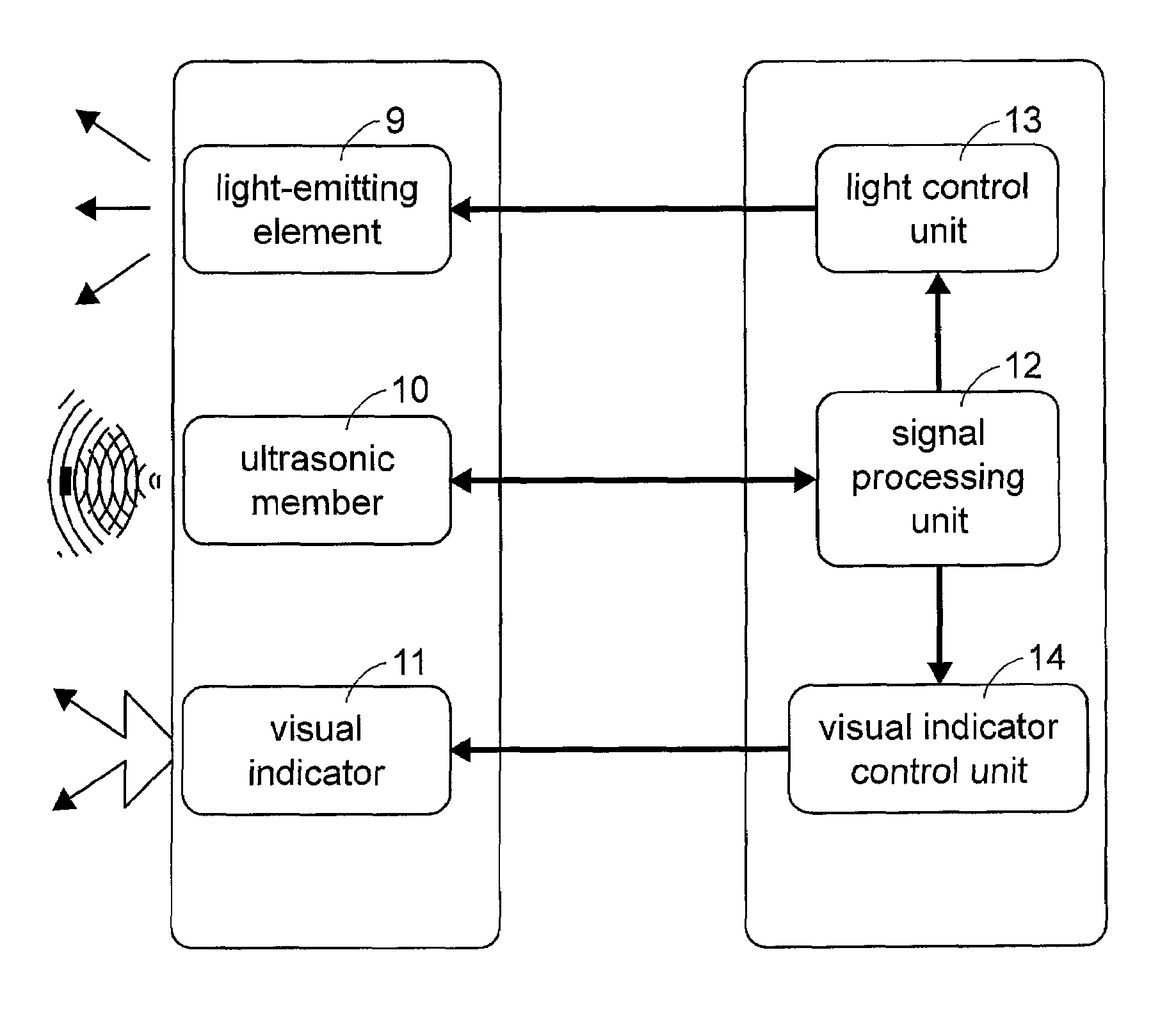
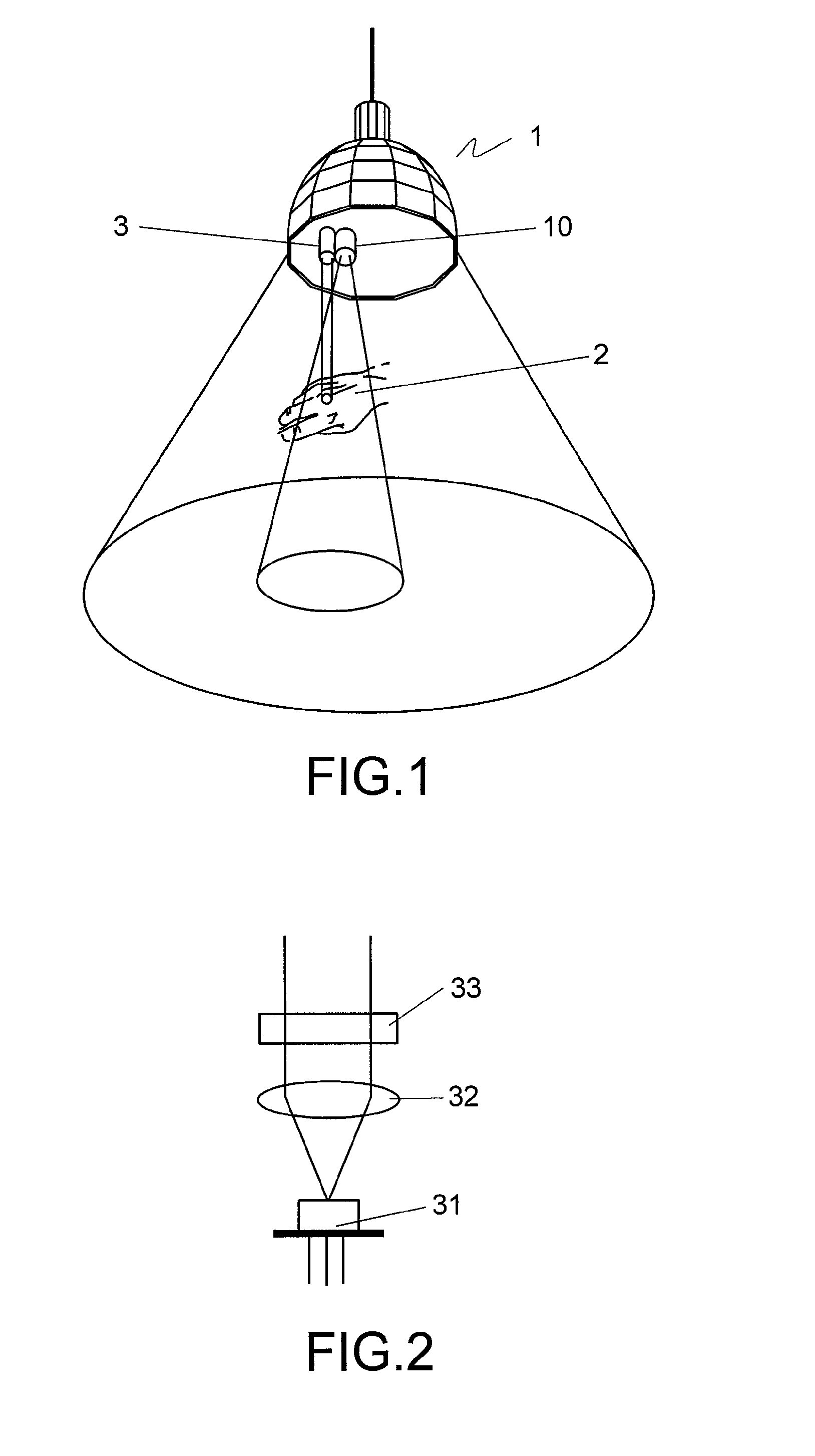
[0027]FIG. 1 schematically illustrates a lighting device with an indicator according to the present invention. The lighting device 1 of FIG. 1 includes one or more light-emitting elements (not shown) and an ultrasonic member 10. Examples of the light-emitting elements include but are not limited to incandescent bulbs or light emitting diodes (LEDs). The ultrasonic member 10 includes an ultrasonic emitter and an ultrasonic receiver. Alternatively, the ultrasonic member 10 can be an ultrasonic transceiver having both function of an ultrasonic emitter and an ultrasonic receiver.

[0028]When the ultrasonic member 10 is in a wait status...


PUM


Abstract

A lighting device includes a light-emitting element, an ultrasonic member, a signal processing unit, a light control unit, an indicator and an indicator control unit. The light-emitting element emits a light. The ultrasonic member emits an ultrasonic signal and receives the ultrasonic signal reflected from an object. The signal processing unit is communicated with the ultrasonic member for converting the reflected ultrasonic signal into a control signal. The light control unit is interconnected between the signal processing unit and the light-emitting element for controlling the light-emitting element to emit light in a selected operating mode in response to the control signal. The indicator control unit is interconnected between the signal processing unit and the indicator for controlling the indicator to assert a notification signal indicative of the operating mode in response to the control signal.

Description

FIELD OF THE INVENTION[0001]The present invention relates to a lighting device, and more particularly to a lighting device with an indicator.BACKGROUND OF THE INVENTION[0002]The use of remote controllers facilitates manipulation of household electrical appliances such as TV sets, video tape recorders, audio equipments, air conditioners, and so on. Recently, a lamp remote controller is used to handle on / off statuses, lighting styles, brightness, and light colors of the lamps. The user can handle the lamp within a distance of several meters from the lamp through the remote controller. Although the use of remote controller to control the lamp is convenient, there are still some drawbacks. For example, the remote controller should be stored in an easily accessible place; otherwise, it becomes quite inconvenient to search the remote controller. In addition, since various kinds of electrical appliances have their own remote controllers, the user is often confused with a lot of remote cont...

Claims


Application Information

Patent Timeline
Patent Type & Authority Patents(United States)
IPC IPC(8): G08B5/00
CPCH05B37/0227H05B47/13H05B47/115Y02B20/40
Inventor LIU, CHIA-YUCHEN, TZU-NAN
Owner LITE ON TECH CORP
Why Eureka
Try Eureka