Throttle arrangement and exhaust system equipped with same

a technology of throttle arrangement and exhaust system, which is applied in the direction of functional valve types, machines/engines, transportation and packaging, etc., can solve the problems of destroying the restoring spring, affecting the life of the restoring spring, so as to achieve the effect of prolonging the life of the throttle arrangemen

Active Publication Date: 2010-10-05
PUREM GMBH
View PDF6 Cites 10 Cited by
  • Summary
  • Abstract
  • Description
  • Claims
  • Application Information

AI Technical Summary

Benefits of technology

[0005]The invention is based on the general idea of supporting the restoring spring symmetrically on the pipe end. As a result, the restoring spring is stressed symmetrically on the pipe end, which makes it possible in particular to prevent or at least reduce any tilting moments about a tilt axis running across the pivot axis; likewise, axial displacement in the direction of the pivot axis can be prevented. On the one hand, this prevents or reduces contact and thus friction between the restoring spring and its support on the pipe end, while on the other hand preventing and / or reducing contact between the throttle valve and the pipe. In the case of a simple leg spring, which has an asymmetrical support, such a tilting moment results in the longitudinal axis of its helical spring section rotating spatially about the tilt axis, such that the helical section of the leg spring comes to rest against the shaft running coaxially through the helical spring section and rubs against the shaft. Furthermore, this tilting moment produces an axial displacement of the throttle valve and tilting of the throttle valve in relation to the pipe. Due to the support designed with mirror symmetry with regard to a plane of symmetry extending in the area of the support of the restoring spring on the valve end, such relative adjustments can be reduced or prevented. It is possible in this way to decrease the abrasive friction effects, which increases the lifetime of the throttle arrangement.
[0006]In an exemplary embodiment, the restoring spring may be formed by a double-leg spring having two helical spring sections connected by a strap section. The double-leg spring is supported on the valve end via the strap section, while it is supported on the pipe end via two free legs. The two helical spring sections are relatively short with regard to the longitudinal direction of the helix, so this reduces the risk of comparatively large relative movements.
[0007]In another exemplary embodiment of the restoring spring designed as a double-leg spring, it is possible to provide in particular for the helical spring sections to be arranged so that they are free-standing between the strap and the free legs, thereby making it possible to prevent contact between the helical spring sections and other components, e.g., the bearing. This free-standing arrangement is made possible due to the symmetrical force support.
[0008]In yet another alternative embodiment, the restoring spring may be designed as a plate spring which is supported via a free end section on the valve end and in particular via a designated holding section on the pipe end. A plate spring can be designed especially easily so that movable areas (apart from the end section) are free of contact with other components and therefore are free of friction.

Problems solved by technology

It has been found that in operation of the throttle arrangement in adjustment of the throttle valve, friction occurs between the restoring spring and neighboring components on the one hand and between the throttle valve and the pipe on the other hand.
Owing to the frequent adjusting movements of the throttle valve that occur during operation of the internal combustion engine, there may be abrasion and therefore weakening of the material of the restoring spring.
In the extreme case, continued friction can destroy the restoring spring.
The restoring spring is then virtually ineffective and the throttle arrangement then fails.
In addition, the throttle valve may also grind on the pipe, making it difficult to operate, and with progressive soiling, it may even jam and ultimately seize up.
This can also lessen the efficacy of the throttle arrangement, leading to total failure.

Method used


Image

  • Throttle arrangement and exhaust system equipped with same
  • Throttle arrangement and exhaust system equipped with same
  • Throttle arrangement and exhaust system equipped with same

Examples


Embodiment Construction

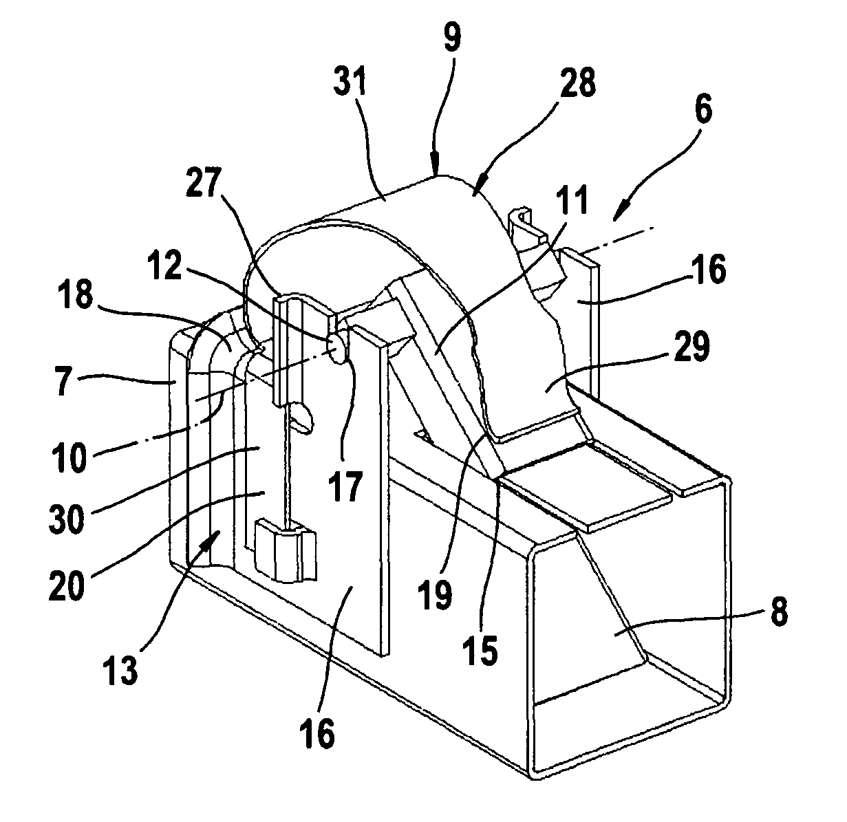
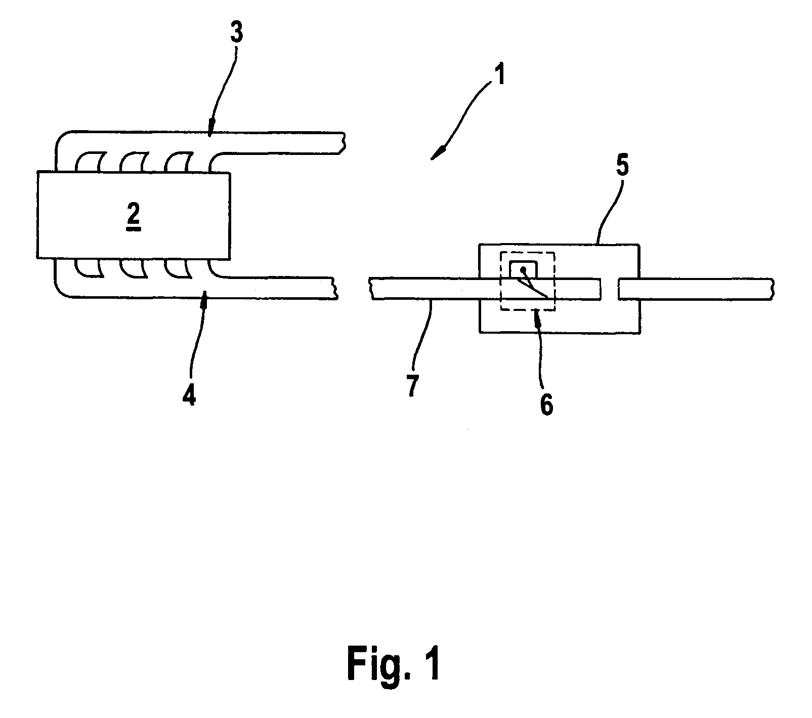
[0017]According to FIG. 1, an internal combustion 1 includes an engine block 2 which is connected to a fresh gas system 3 for supplying fresh gas, in particular fresh air, and an exhaust gas system 4 for removing the exhaust gas. The exhaust system 4 includes in the usual manner (not shown here) exhaust gas purification equipment, e.g., a particulate filter and / or at least one catalytic converter and muffler equipment. A rear muffler 5 is shown here only as an example. The exhaust system 4 has at least one throttle arrangement 6 with the help of which the exhaust stream can be controlled as a function of the exhaust pressure in a pipe 7 of the exhaust system 4. The pipe 7 is formed by an exhaust line of the exhaust system 4. In the example shown here, the throttle arrangement 6 is arranged in the rear muffler 5. Another position of the throttle arrangement 6 within the exhaust system 4 is also possible.

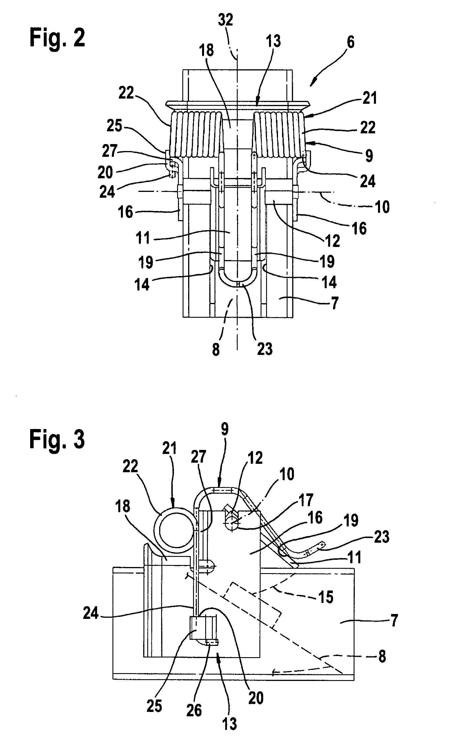
[0018]According to FIGS. 2 through 5, the throttle arrangement 6 includes a throt...


PUM


Abstract

The invention relates to a throttle arrangement for an exhaust system of an internal combustion engine having a throttle valve for throttling a stream of exhaust gas flowing through a pipe and having a restoring spring which prestresses the throttle valve into a closed position. The throttle valve is pivotable about a pivot axis in the pipe between the closed position [and the open position] and the restoring spring is supported on the valve end on a lever fixedly connected to the throttle valve and is supported at the pipe end on a bearing for accommodating a shaft extending coaxially with the pivot axis. The restoring spring is adapted to support the spring forces on the pipe end in an essentially symmetrical manner with respect to a plane of symmetry that extends perpendicular to the pivot axis and is in the area of the support on the valve end.

Description

FIELD OF THE INVENTION[0001]The present invention relates to a throttle arrangement for an exhaust system of an internal combustion engine and to an exhaust system equipped with such a throttle arrangement as well.BACKGROUND OF THE INVENTION[0002]DE 103 04 364 A1 describes a throttle arrangement and an exhaust system of the type defined above. The known throttle arrangement includes a throttle valve for throttling an exhaust gas stream flowing through a pipe and a restoring spring applying prestress to the throttle valve pulling it into the closed position. The throttle valve is pivotable about a pivot axis in the pipe between the closed position, in which it at least partially closes a predetermined cross-sectional area of the pipe, and an open position, in which it releases the cross-sectional area due to the pressure of the exhaust gas against the spring force of the restoring spring. With the known throttle arrangement, the restoring spring is designed as a leg-spring whose heli...

Claims


Application Information

Patent Timeline
Patent Type & Authority Patents(United States)
IPC IPC(8): F01N1/00F16K15/00F16K17/00F16K21/04F16K1/16F01N13/08
CPCF02B27/06F02D9/08F02D9/1025F02D9/107Y02T10/146Y02T10/12Y10T137/7898
Inventor HANITZSCH, ROBERTDAMSON, BJOERN
Owner PUREM GMBH
Why Eureka
Try Eureka