Panel mounted appliance elevator apparatus

a technology for elevators and appliances, applied in the field of furniture making, can solve the problems of increasing labor costs, increasing labor costs for furniture manufacturers, intense competitiveness of the furniture industry, etc., and achieves the effects of convenient handling of the lift mechanism, rapid and easy positioning, and easy grasping

Inactive Publication Date: 2010-10-05
IMPORTADVANTAGE
View PDF29 Cites 37 Cited by
  • Summary
  • Abstract
  • Description
  • Claims
  • Application Information

AI Technical Summary

Benefits of technology

[0014]In accordance with the invention, the above-noted drawbacks and disadvantages of the prior art are overcome by providing an appliance elevator apparatus having an appliance lift mechanism which, prior to installation in a piece of furniture, is mounted to a substantially planar mounting panel which defines a mounting plane oriented substantially parallel to the line of travel of the lift mechanism. At least a portion of the mounting panel extends beyond the periphery of the body of the lift mechanism in at least one direction oriented substantially perpendicular to the line of travel. To facilitate handling of the lift mechanism, this extending portion of the mounting panel optionally includes one or more hand openings of sufficient size to permit the mounting panel and lift mechanism mounted thereon to be easily grasped and maneuvered into position as a unit within the interior cavity of the furniture in which the apparatus is to be installed. The extending portion of the mounting panel

Problems solved by technology

The furniture industry is intensely competitive and cost sensitive.
The time required to carry out such an assembly within the limited space available inside the furniture is not insubstantial and can significantly increase the labor costs borne by the furniture manufacturer.
Those labor costs are increased, not only because of the actual time required to perform the assembly inside the furniture, but also by the necessity of having the work performed by installers having significant skill and training as well as manual dexterity.
Thus, training costs are multiplied if the furniture manufacturer uses several different types of lifts.
The cost and time required to train installers limits the flexibility of furniture manufacturers to substitute lifts of one type for another or to begin use lifts of a different type in order to take advantage of lower prices, better quality, design improvements or more reliable sources of supply.
However, this approa

Method used


Image

  • Panel mounted appliance elevator apparatus
  • Panel mounted appliance elevator apparatus
  • Panel mounted appliance elevator apparatus

Examples


Embodiment Construction

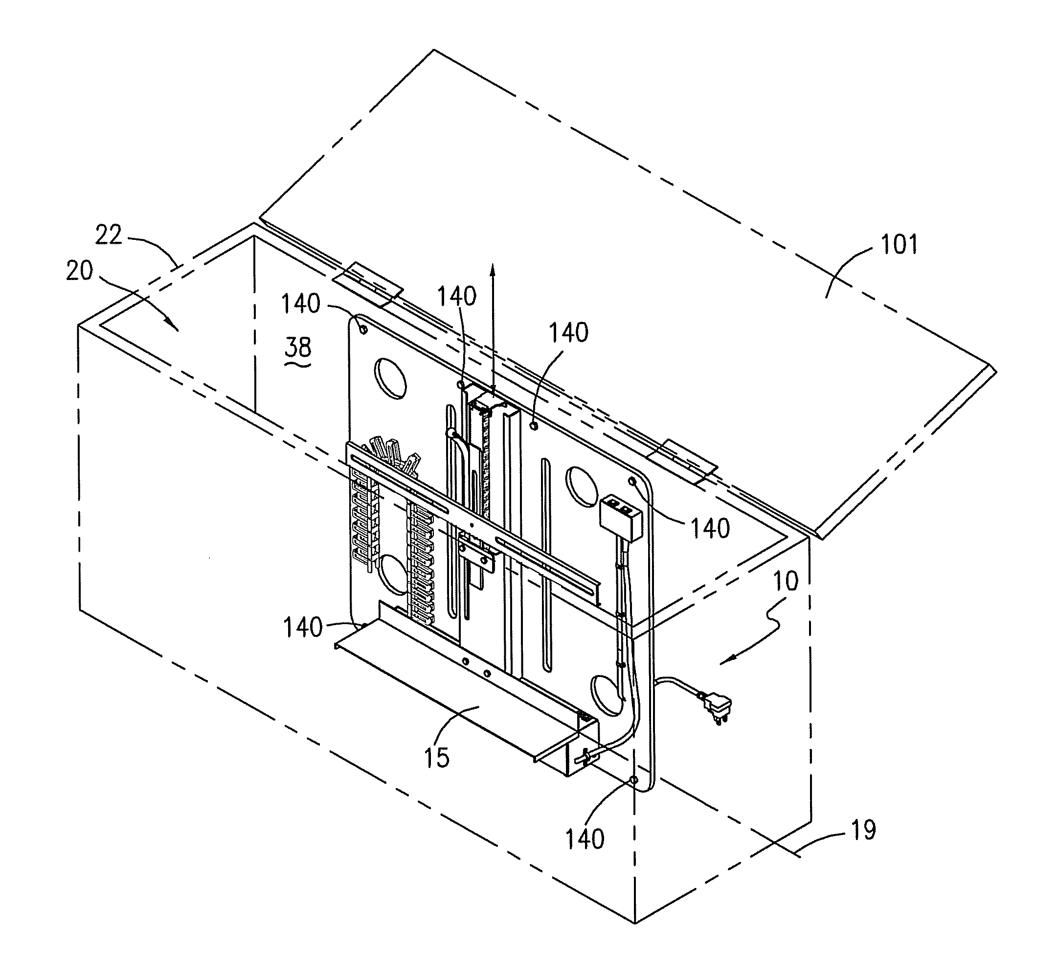
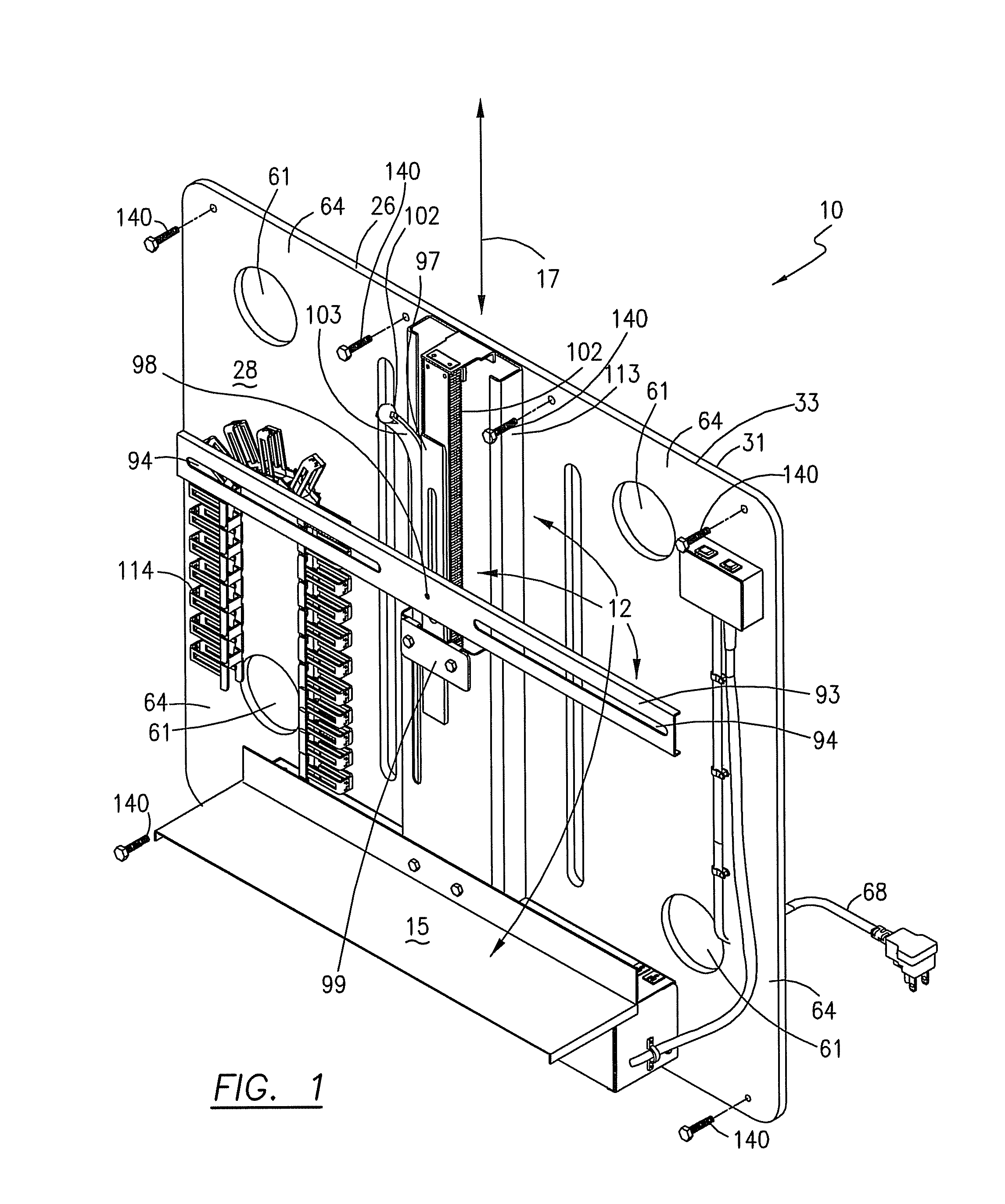
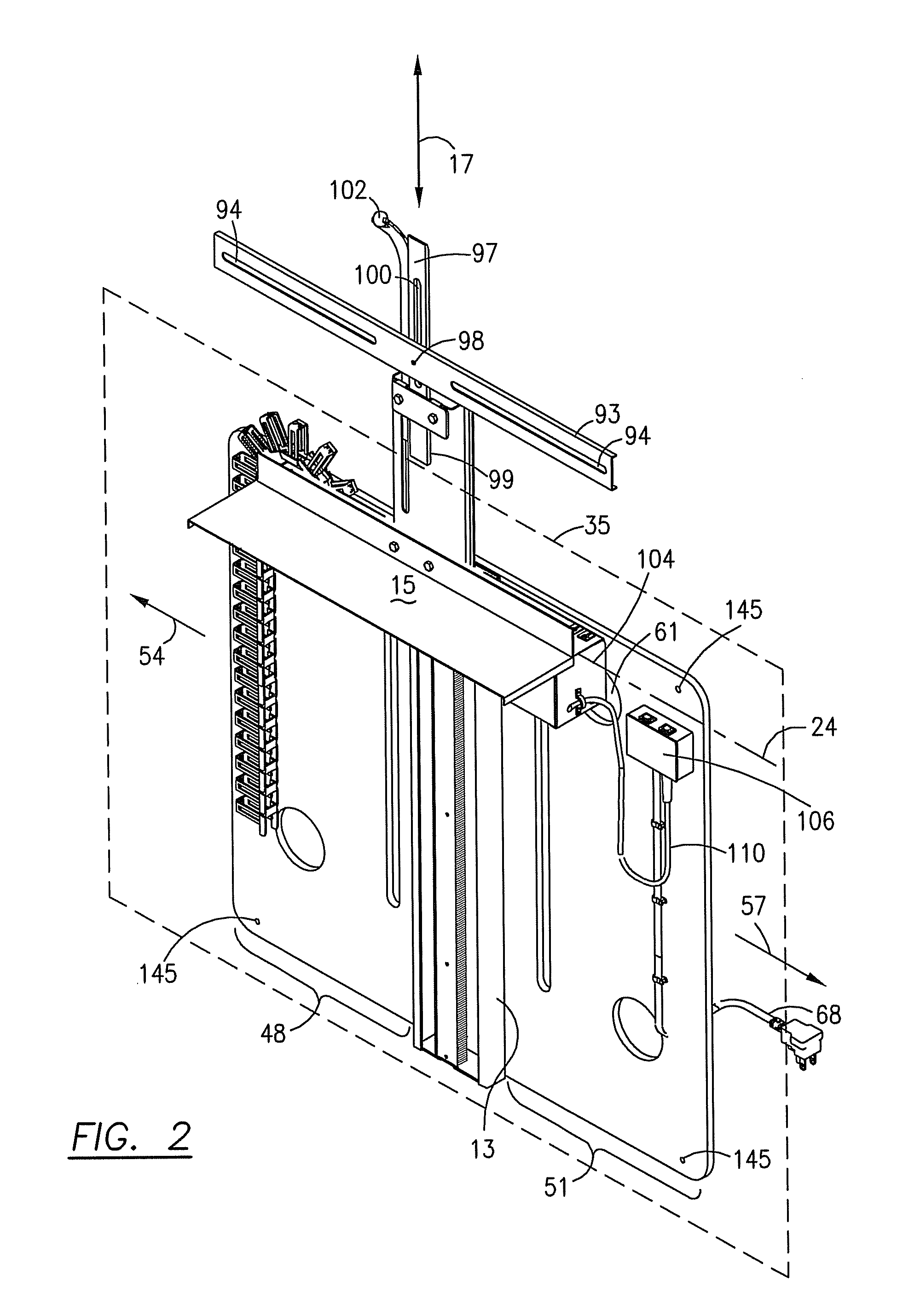
[0022]FIGS. 1-7 illustrate a preferred embodiment of a panel-mounted appliance elevator 10 constructed according to the present invention. Elevator 10 includes a power-driven lift mechanism 12 which has a stationary body 13 to which a movable appliance support 15 is mounted for holding a television or other household appliance (not shown). Lift mechanism 12 includes an electric motor 14 and a drive unit 16 which is mechanically interposed between the motor and the appliance support to selectively move the appliance support 15, and thus the appliance it carries (not shown), along a line of travel 17 between a lowered, storage position 19, as shown in FIG. 1, for storing the appliance concealed within the interior cavity 20 of a piece of furniture 22 within which elevator 10 is installed, and a raised, use position 24, as shown in FIG. 2 for making the appliance accessible for its normal intended use.

[0023]In accordance with the invention, the body 13 of lift mechanism 12 is mounted u...


PUM


Abstract

An appliance elevator includes a lift mechanism mounted to a substantially planar mounting panel at least a portion of which extends beyond the body of the lift mechanism to provide an area by way of which the mounting panel and lift mechanism pre-mounted on the mounting panel can be easily positioned within a piece of furniture and attached to the furniture by way of one or more fasteners such that substantially the entire mechanical load on the lift mechanism when it is in use is transferred to the furniture by way of the mounting panel.

Description

CROSS-REFERENCE TO RELATED APPLICATIONS[0001]Not Applicable.STATEMENT REGARDING FEDERALLY SPONSORED-RESEARCH OR DEVELOPMENT[0002]Not Applicable.INCORPORATION BY REFERENCE OF MATERIAL SUBMITTED ON A COMPACT DISC[0003]Not Applicable.FIELD OF THE INVENTION[0004]The invention relates to the field of furniture making. More particularly, the invention relates to a panel-mounted elevator apparatus installable within a piece of furniture for supporting a household or office appliance, such as a television, television monitor, computer monitor or the like, and for selectively raising the appliance from within the furniture for use and lowering the appliance into the furniture for storage when the appliance is not in use.BACKGROUND OF THE INVENTION[0005]It has become popular in recent years to manufacture home and office furniture items which include an internally mounted, power-driven elevator for supporting an appliance such as a television, television monitor, computer monitor or the like ...

Claims


Application Information

Patent Timeline
IPC IPC(8): A47B51/00
CPCA47B81/064
Inventor BUEHL, ROBERT C.
Owner IMPORTADVANTAGE
Why Eureka
Try Eureka