Permanent magnet motor

a permanent magnet, magnet technology, applied in the direction of magnetic circuits, electrical apparatus, dynamo-electric machines, etc., can solve the problems of more copper loss to fail effectively to upgrade and achieve the effect of reducing the harmonic composition, reducing the change of flux vector, and improving the performance efficiency of the motor

Inactive Publication Date: 2010-10-05
RECHI PRECISION
View PDF10 Cites 33 Cited by
  • Summary
  • Abstract
  • Description
  • Claims
  • Application Information

AI Technical Summary

Benefits of technology

[0008]The primary purpose of the present invention is to provide a permanent magnet motor that lowers high harmonic composition contained in start power wave form by reducing change of flux vector so to sufficiently upgrade the performance efficiency of the motor.

Problems solved by technology

Given with the situation, number of windings of the stator coil must be increased so to provide higher start power induced at where the stator coil is located; however, the stator coil will cause more copper loss to fail effectively upgrade performance efficiency of the motor.

Method used


Image

  • Permanent magnet motor
  • Permanent magnet motor
  • Permanent magnet motor

Examples


Embodiment Construction

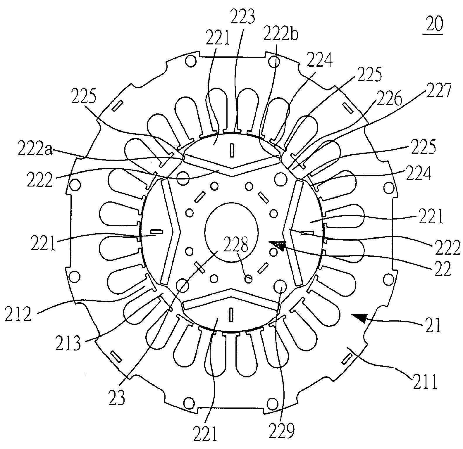
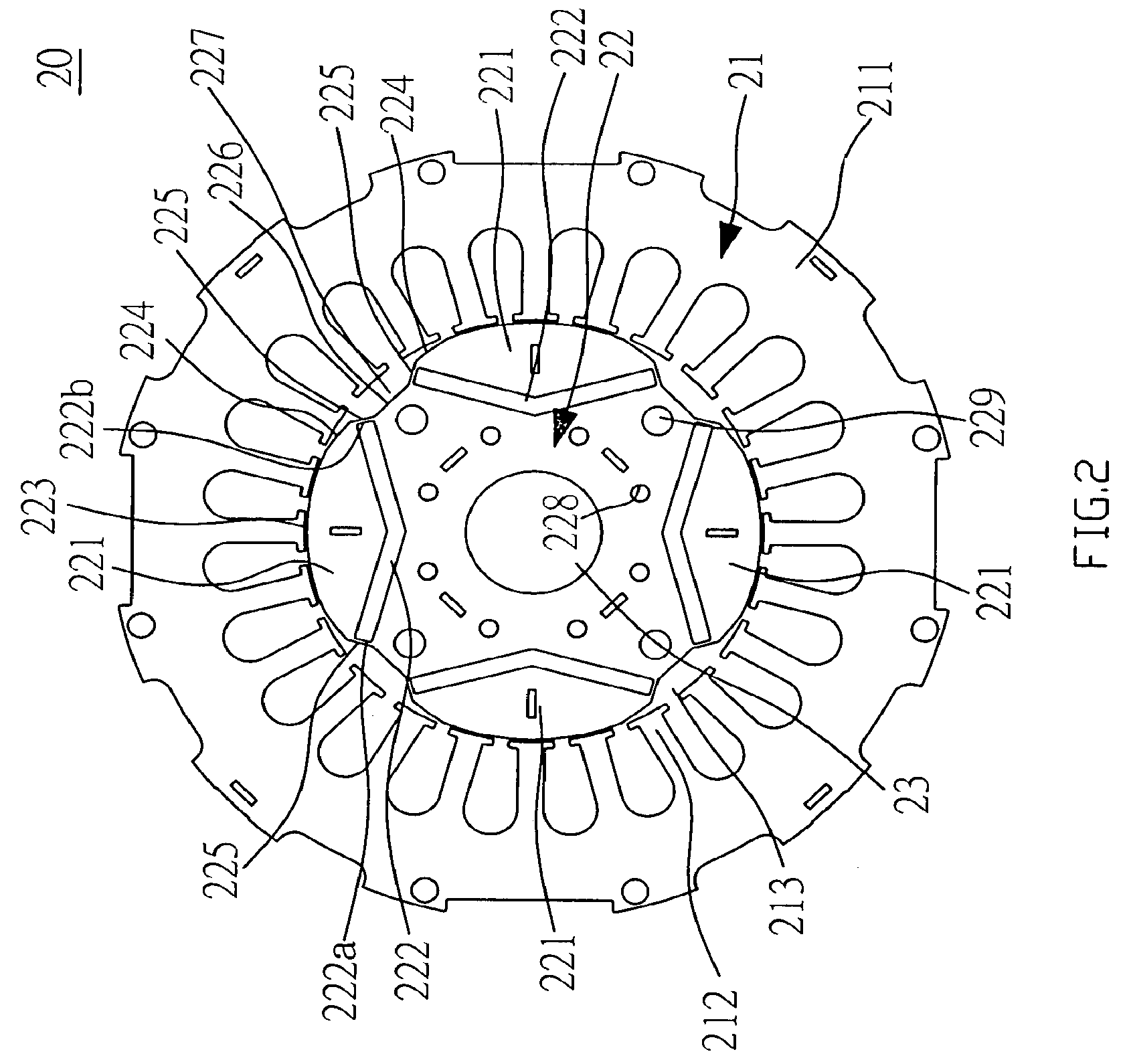
[0016]The present invention is essentially related to an improved construction of a rotor in an ordinary permanent magnet motor. Referring to FIGS. 2, 3, and 4, a permanent magnet motor 20 is comprised of a stator 21, a rotor 22, and a shaft 23. Wherein the stator 21 includes a ring body 211 and multiple stator magnetic poles 212; each stator magnetic pole 212 protrudes from interior of the ring body 211; and an accommodation room 213 is formed in each stator magnetic pole 212.

[0017]The rotor 22 related to a plate approximately indicating a circular form is provided in the accommodation room 213 and keeps an air gap from each stator magnetic pole 212. The rotor 22 is disposed with multiple rotor magnetic poles 221 provided in even numbers with each pole 221 disposed with a magnet 222. In the preferred embodiment, a 4-pole motor is provided; therefore, there are four rotor magnetic poles 221. Each rotor magnetic pole 221 is disposed with an arc surface 223, and a first inclined secti...


PUM


Abstract

A permanent magnet motor includes stator, rotor, and shaft; multiple rotor magnetic poles are disposed on the rotor; each rotor magnetic pole contains an arc surface and a first inclined section and a second inclined section extending respectively from both sides of the arc surface; a trap is formed between two second inclined section of two abutted rotor magnetic poles connected by a tangent section; multiple magnets are respectively disposed in each rotor magnetic pole; both ends of each magnet being disposed at where close to two second inclined sections; and a central portion of each magnet is indented inwardly towards a center of the rotor to effectively upgrade performance efficiency of the motor.

Description

BACKGROUND OF THE INVENTION[0001](a) Field of the Invention[0002]The present invention is related to a permanent magnet motor, and more particularly, to one that lowers high harmonic composition contained in start power wave form by reducing change of flux vector so to sufficiently upgrade its performance efficiency.[0003](b) Description of the Prior Art[0004]Motor is a popular source of motive force in the manufacturing industry today where supply of motive force is needed to drive machines to execute rotation or other forms of motion. Whereas the motor is capable of converting electric power or magnetic power into mechanical power, it has become a must and is comprehensively applied in various types of industrial, electric appliance, and transportation system installations.[0005]Motors are generally available in DC, AC, brush, and brushless. A motor is essentially comprised of a rotor and a stator. Distribution of magnetic flux promotes the rotor to engaging in rotary motion, whic...

Claims


Application Information

Patent Timeline
Patent Type & Authority Patents(United States)
IPC IPC(8): H02K21/12
CPCH02K1/2766H02K29/03
Inventor LEE, SIMONYU, WEN-HO
Owner RECHI PRECISION
Why Eureka
Try Eureka