
Method for analyzing data and data analysis apparatus

a data analysis and data technology, applied in the field of log analysis methods or apparatuses, can solve the problems of time discontinuity, difficult integration of timings of recording time stamps, and increasing load on the network, so as to prevent discontinuity of time stamps and correct understanding

Inactive Publication Date: 2010-10-05
HITACHI LTD
View PDF30 Cites 5 Cited by
  • Summary
  • Abstract
  • Description
  • Claims
  • Application Information

AI Technical Summary

Benefits of technology

The invention provides a method for analyzing logs from multiple computers by correcting time stamps to eliminate shifting and ensure consistency in analysis. This is necessary because shifting in time stamps can occur between logs from different computers, and the conventional method of using time stamps based on the Network Time Protocol (NTP) can cause problems such as increased network load and time discontinuity. The invention uses a consistency check result of logs and a time correction log to determine the correct time stamps for analysis. This ensures that logs from different computers have consistent timestamps and reduces the likelihood of phantom events. The invention can be used in various log analysis applications where consistency is important.

Problems solved by technology

When time correction based on the NTP is carried out highly frequently in a large system, loads on a network increase.
To the contrary, the frequent time correction may cause a problem of time discontinuity.
Integration of timings of recording time stamps is practically difficult to realize, because detection timing of an event to be recorded in a log or a monitor value has to be adjusted, and time necessary for obtaining time to be set as a time stamp has to be taken into consideration in hardware or software for outputting logs.

Method used


Image

  • Method for analyzing data and data analysis apparatus
  • Method for analyzing data and data analysis apparatus
  • Method for analyzing data and data analysis apparatus

Examples


first embodiment

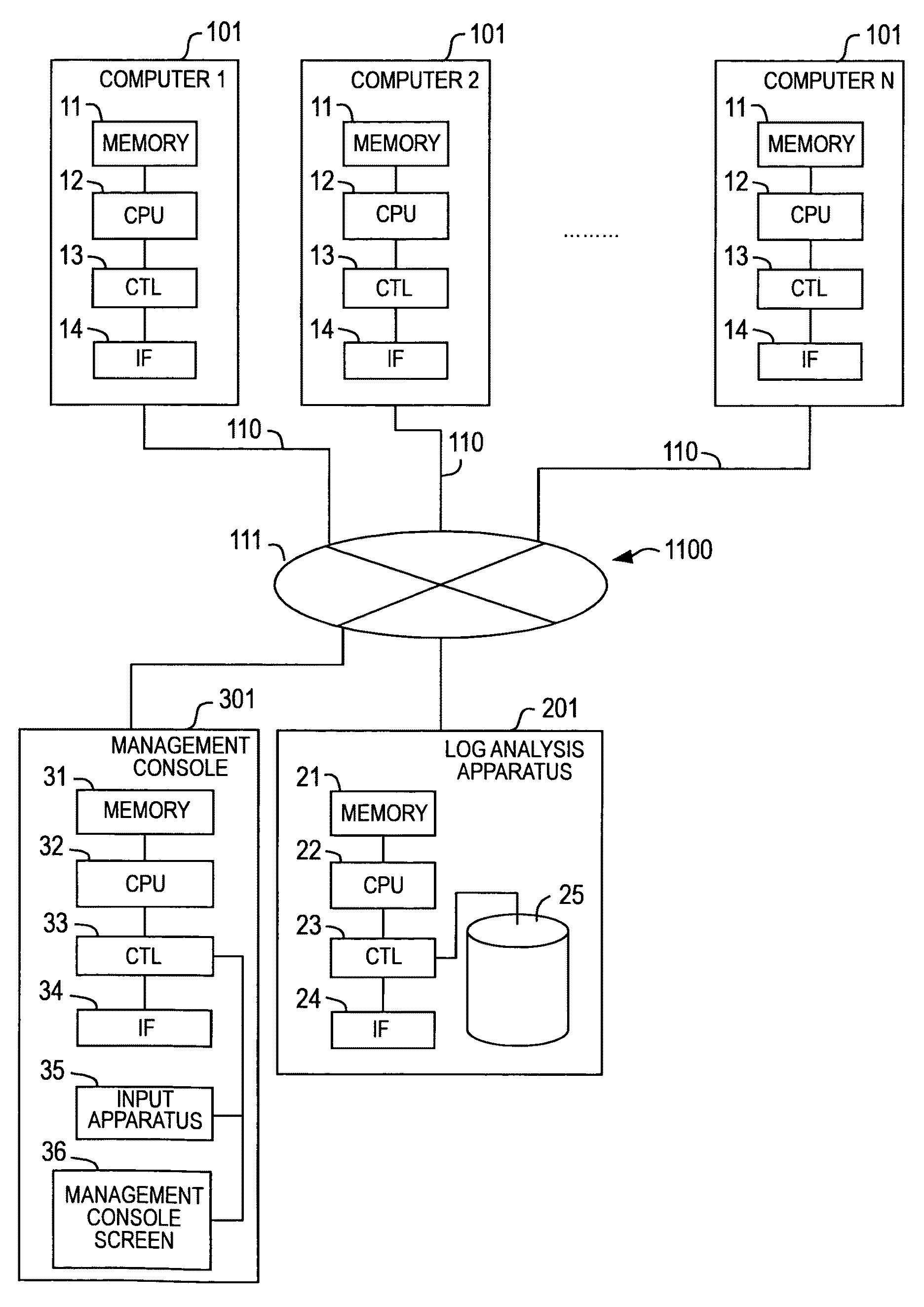
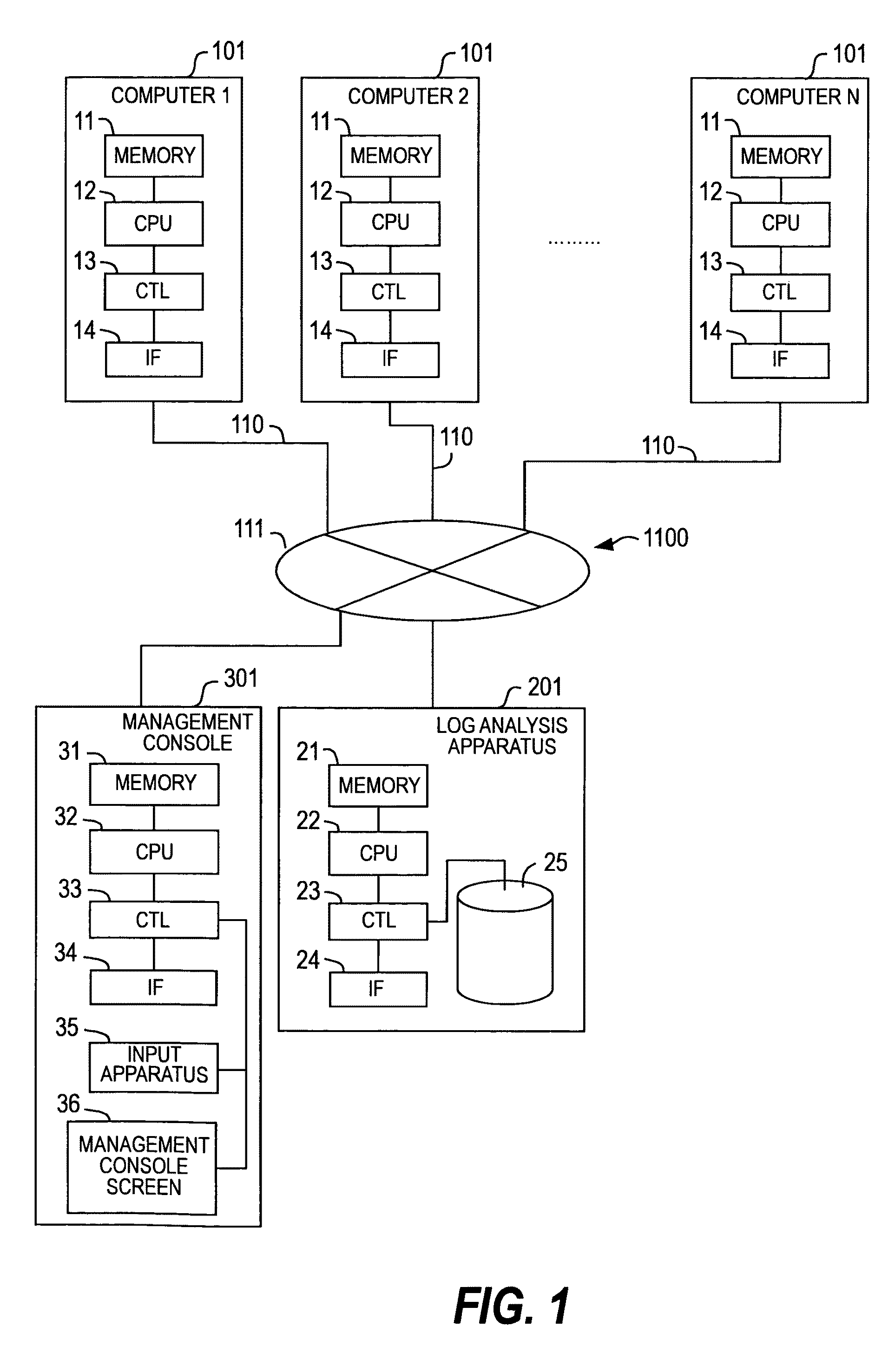
[0051]FIGS. 1 to 16 illustrate a first embodiment of this invention. FIG. 1 is a block diagram illustrating a configuration of a computer system to which this invention is applied.

[0052]Referring to FIG. 1, in the computer system to which this invention is applied, a plurality of computers 101 of a cluster configuration are coupled to a network 1100, and a log analysis apparatus 201 that collects and analyzes logs output from the computers 101 is coupled to the network 1100. Each computer 101 includes a memory 11 for storing data or commands, a CPU (processor) 12 for executing an arithmetic operation, an interface 14 coupled to the network 1100, and a control unit 13 for controlling data between the CPU 12 and the interface 14. A storage system can be coupled to the control unit 13. The plurality of computers 101 (computers 1 to N) execute predetermined processes. For example, when a web 3-tier system is configured, the computer 1 operates a web server, the computer 2 operates an ap...

second embodiment

[0124]Referring to FIGS. 17 and 18, a log analysis apparatus according to a second embodiment of this invention will be described.

[0125]FIG. 17 is a block diagram illustrating a computer system according to the second embodiment of this invention. The computer system of FIG. 17 includes at least one computer 1501, a log analysis apparatus 1502, a management console 1503, and a network 1504.

[0126]In FIG. 17, the log analysis apparatus 1502 and the management console 1503 are coupled to the network 1504 as apparatuses separate from the computer 1501. However, these apparatuses may be present in the computer 1501, and a network for interconnecting the log analysis apparatus 1502 and the management console 1503 may be independent of a network for interconnecting the computer 1501 and the log analysis apparatus 1502. The computer 1501 generates logs, and the log analysis apparatus 1502 collects and analyzes the logs generated by the computer 1501. All or some apparatuses included in this...


PUM


Abstract

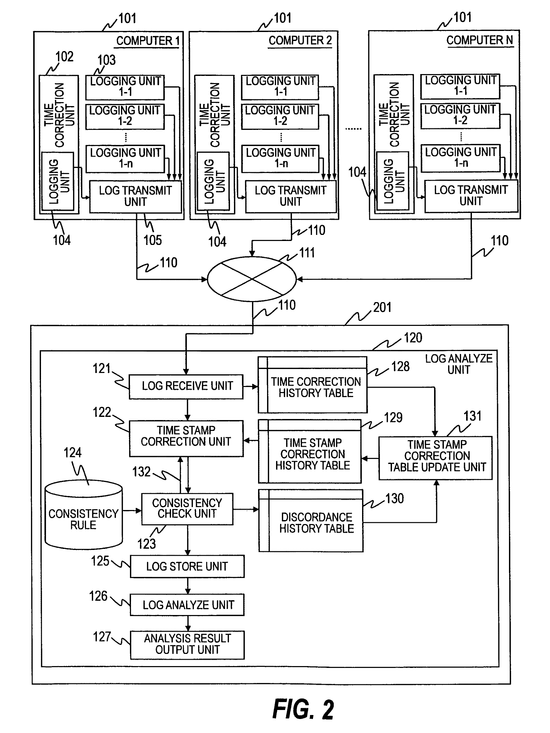
When logs are analyzed, an analysis with consistency is carried out on the presumption that shifting occurs among time stamps of logs output from a plurality of apparatuses engaged in time correction amount. In a log analysis apparatus which receives logs from a plurality of computers for generating a plurality of logs for analysis, for the plurality of logs output from the plurality of computers, a time stamp recorded in each log is corrected based on a time correction log according to a consistency rule among the logs.

Description

CLAIM OF PRIORITY[0001]The present application claims priority from Japanese application P2007-108447 filed on Apr. 17, 2007, the content of which is hereby incorporated by reference into this application.BACKGROUND OF THE INVENTION[0002]This invention relates to a log analysis method or apparatus which monitors a system status or inquires into a problem by using a plurality of logs, and more particularly, to a method or an apparatus for correcting a time stamp recorded in a log by using a time correction log of an apparatus which has output the log, and a rule regarding time stamps of logs in order to correctly understand an event recorded in a log, and an order relation or correlation of monitor values etc., and to correctly determine the system status or a cause of the program.[0003]Rendering services by using a cluster system which includes a plurality of computers such as a web 3-tier system (application system) has gained in popularity, increasing a necessity of continuously p...

Claims


Application Information

Patent Timeline
Patent Type & Authority Patents(United States)
IPC IPC(8): G06F17/30
CPCH04L43/0817H04L43/106
Inventor NAKAMURA, TOMOHIRO
Owner HITACHI LTD
Learn More