Double-vortex fluid separator

a separator and vortex tube technology, applied in the direction of separation process, auxillary pretreatment, dispersed particle separation, etc., can solve the problems of reducing the ability of the vortex tube to separate liquid from gas, awkward assembly of parts, and limitations of centrifugal separation methods. achieve the effect of promoting oil separation

Inactive Publication Date: 2010-10-12
DUKE BOBBY RAY +1
View PDF20 Cites 37 Cited by
  • Summary
  • Abstract
  • Description
  • Claims
  • Application Information

AI Technical Summary

Benefits of technology

[0009]Another object of some embodiments is join two generally conical tubes such that their longitudinal centerlines diverge, whereby the discharge from each tube points in at least a slightly different direction to help create a calmer pool of liquid into which the separated liquid discharges. The

Problems solved by technology

Current methods of centrifugal separation, however, have their limitations and drawbacks.
If a larger diameter vortex tube is used to accommodate a larger inlet pipe, the resulting lower flow velocity and larger helix diameter reduces the centrifugal force and thus reduces the vortex tube's ability to separate liquid from gas.
Such a

Method used


Image

  • Double-vortex fluid separator
  • Double-vortex fluid separator
  • Double-vortex fluid separator

Examples


Embodiment Construction

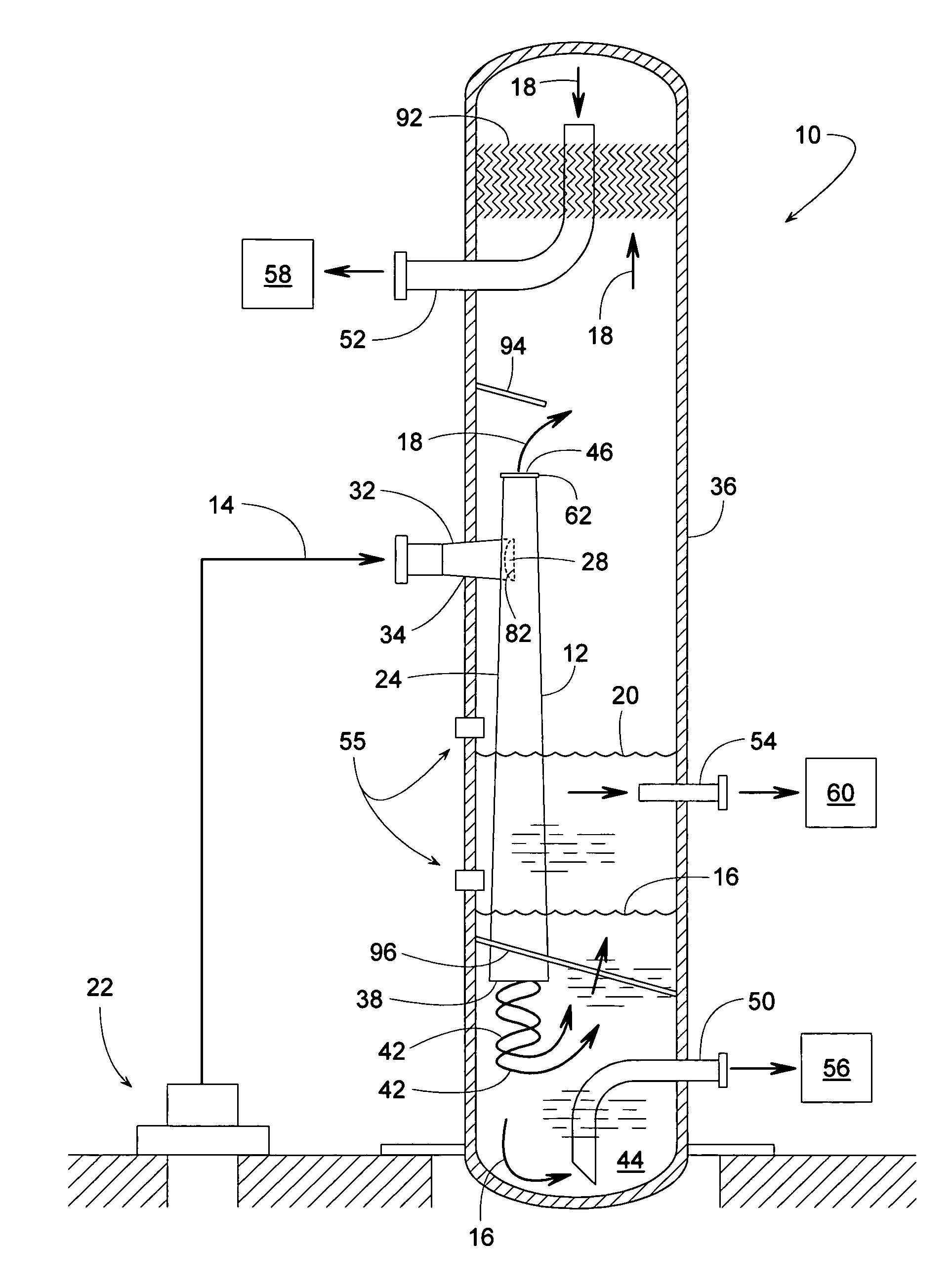
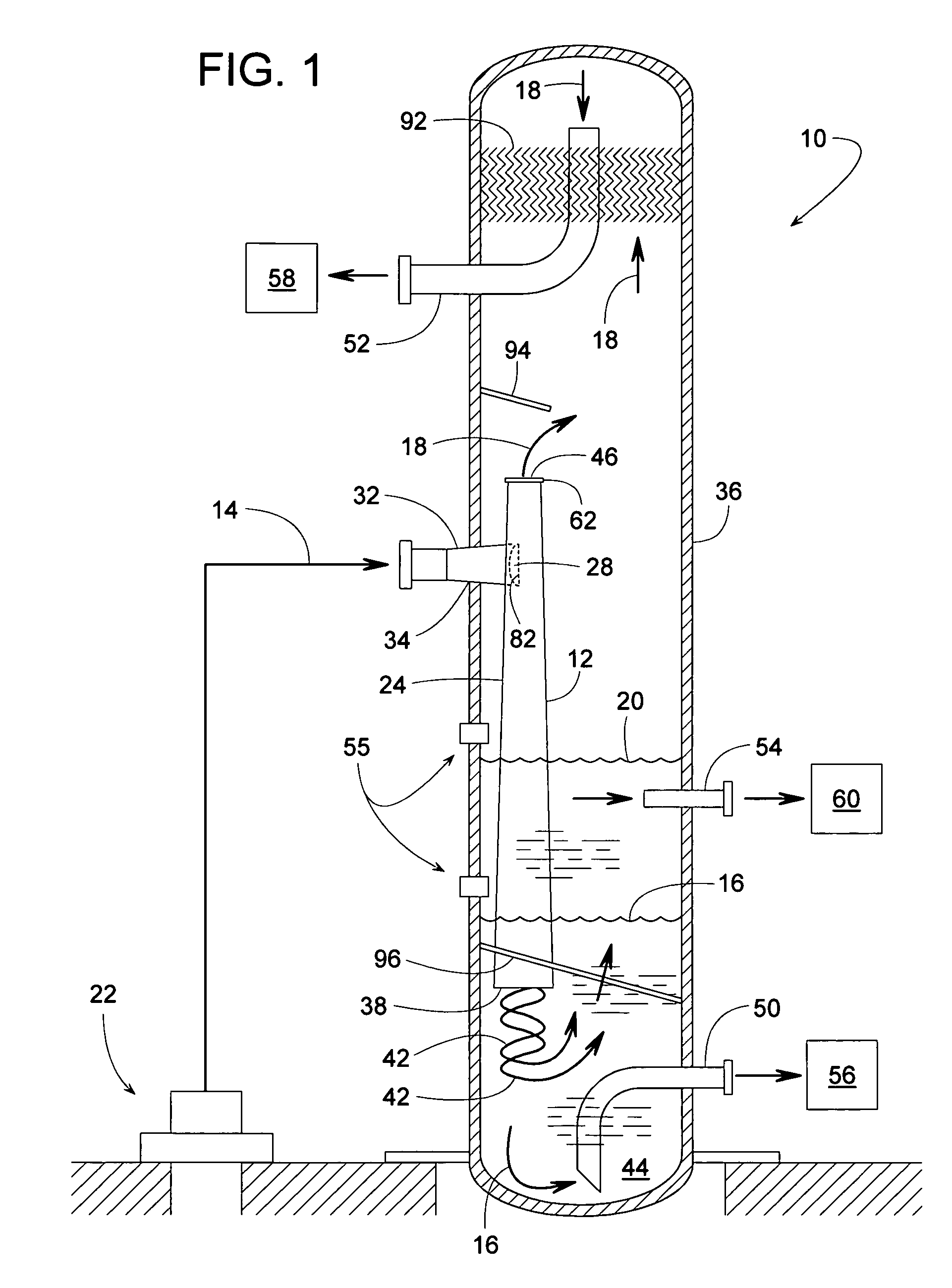
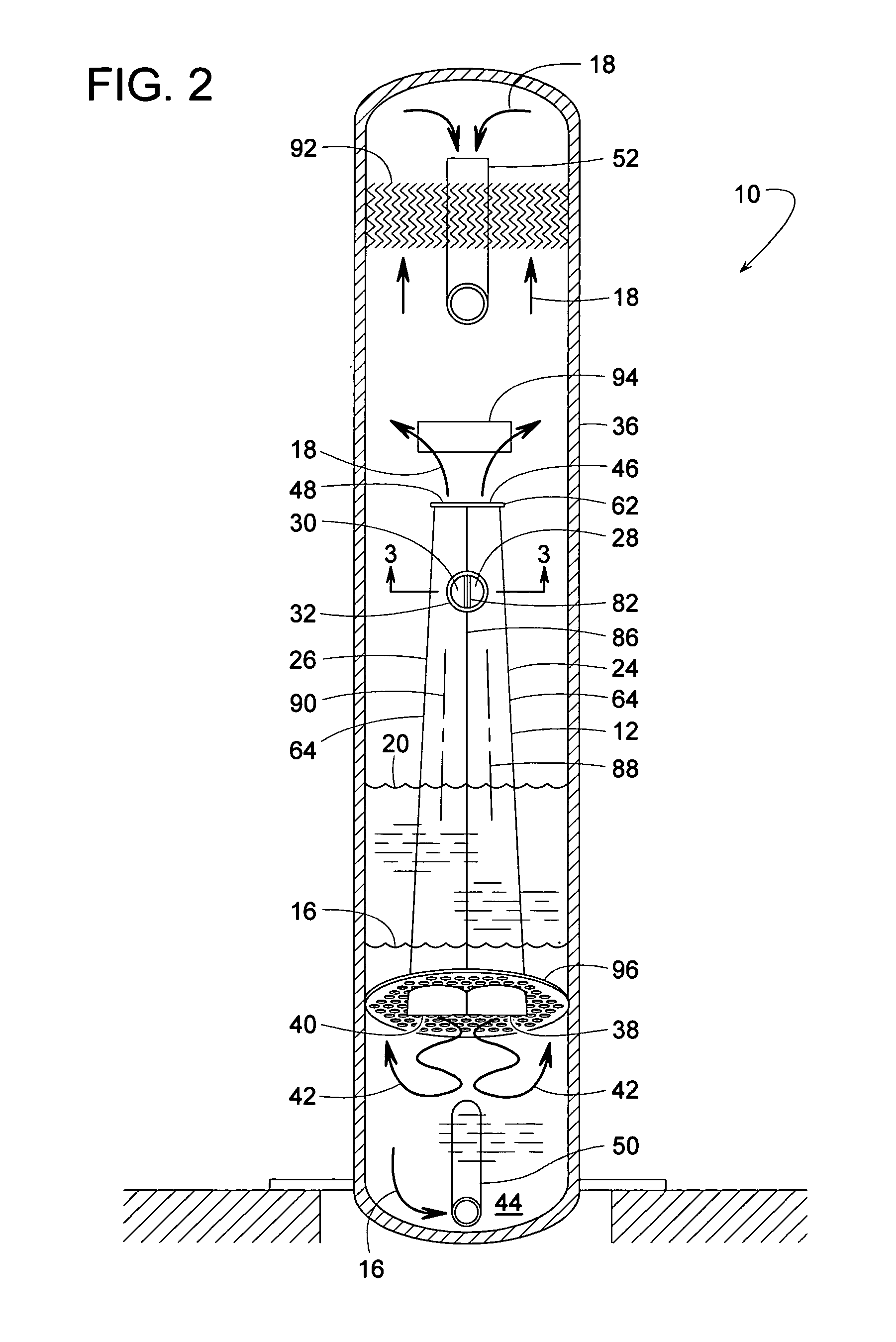
[0023]FIGS. 1 and 2 illustrate a fluid separator 10 with a double-vortex generator 12 that can separate an incoming fluid 14 into its component parts of water 16, gas 18 and oil 20. The proportion of any one component can range from zero to 100% and can fluctuate or change over time. Although separator 10 is particularly suited for processing fluid pumped from an oil well 22, separator 10 could be applied to other applications.

[0024]In some embodiments, generator 12 comprises two vortex tubes 24 and 26 with respective fluid inlets 28 and 30 that are fed with fluid 14 via a common inlet pipe 32. Inlet pipe 32 is connected to an inlet 34 of a vertically elongate pressure vessel 36. As fluid 14 from inlet pipe 32 enters tubes 24 and 26 tangentially through inlets 28 and 30, the fluid swirls helically in opposite rotational directions within tubes 24 and 26. The resulting centrifugal force slings the fluid's heavier components, oil and / or water, against the inner wall of tubes 24 and 26...


PUM

PropertyMeasurementUnit
Pressureaaaaaaaaaa
Flow rateaaaaaaaaaa

Abstract

A fluid separator includes a side-by-side double-vortex fluid generator installed within a pressure vessel. The vortex generator separates the liquid and gas components of the incoming fluid mixture, and the vessel itself helps further separate the liquid into water and oil components, which makes the fluid separator particularly suited for processing fluids extracted from an oil well. The generator includes two diverging vortex tubes each having a polygonal cross-section. Such a cross-section allows the tubes to be formed using a conventional press brake. The vortex tubes also have diverging longitudinal centerlines to help spread the liquid flow pattern discharging into the vessel.

Description

FIELD OF THE INVENTION[0001]The subject invention generally pertains to the separation of gas, oil and water, and more specifically pertains to a vortex-style separator.BACKGROUND OF RELATED ART[0002]Forcing a fluid mixture of liquid and gas in a helical flow pattern through a cyclone separator or vortex tube can centrifugally separate the liquid from the gas. In the right applications, this process is effective and widely used. Current methods of centrifugal separation, however, have their limitations and drawbacks.[0003]Since the incoming fluid is injected tangentially into the side of a vortex tube, the diameter of the inlet feed pipe is typically smaller than that of the vortex tube. A relatively small diameter inlet pipe creates a flow restriction that can reduce the separator's flow rate capacity. If a larger diameter vortex tube is used to accommodate a larger inlet pipe, the resulting lower flow velocity and larger helix diameter reduces the centrifugal force and thus reduce...

Claims


Application Information

Patent Timeline
IPC IPC(8): B01D45/12
CPCB01D45/16
Inventor DUKE, BOBBY RAYLUXTON, CLARENCE M.
Owner DUKE BOBBY RAY
Why Eureka
Try Eureka