Modular wireless lighting control system using a common ballast control interface

a wireless and wireless technology, applied in the field of lighting systems, can solve the problems of high labor intensity, general cost prohibitive, and high implementation cost, and achieve the effects of reducing energy consumption, reducing labor intensity, and facilitating and more effective ways of controlling lighting

Inactive Publication Date: 2010-10-12
BUDIKE JR LOTHAR E S
View PDF13 Cites 76 Cited by
  • Summary
  • Abstract
  • Description
  • Claims
  • Application Information

AI Technical Summary

Benefits of technology

[0010]Accordingly, one advantage of the present invention is that it reduces the expense of updating or retrofitting existing buildings with more efficient and advanced lighting control products.
[0011]Another advantage of the present invention is that it provides easier and more effective ways of controlling lighting to minimize energy consumption.
[0012]Still another advantage of the present invention is that it reduces the number of different types of lighting components used in a given structure.
[0013]Additional advantages of the invention will be set forth in the description that follows, and in part will be apparent from the description, or may be learned by practice of the invention. The advantages of the invention will be realized and attained by the structure pointed out in the written description and claims hereof as well as the appended drawings
[0014]To achieve these and other advantages, the present invention involves a lighting control system. The lighting control system comprises a transceiver having a data processing unit, an interface circuit, and a first plug that is connected to a first end of an interface cable; and a dimming ballast connected to a second end of the interface cable, wherein the dimming ballast is configured to provide a voltage to power the transceiver, and the transceiver is configured to provide an on / off control to the dimming ballast.
[0015]In another aspect of the present invention, the aforementioned and other advantages are achieved by a lighting control system, which comprises a sensor; a power interface connected to the sensor by an interface cable; and a ballast connected to the power interface, wherein the power interface is configured to provide, over the interface cable, a voltage to power the sensor, and wherein the sensor is configured to provide, over the interface cable, an on / off signal to the ballast.

Problems solved by technology

Central lighting control based on time of day, motion, and ambient sunlight, are expensive to implement.
First, they are expensive to install because each individual circuit line feeder must be wired back to a central system.
In many cases, these lighting systems are retrofitted into existing buildings, which is extremely labor intensive and generally cost prohibitive, especially in large commercial office buildings.
Further, related art central lighting control systems are restricted to on / off functionality, because they rely on the use of relays.
As such, dimming control is generally not available in a central lighting control system.
Second, lighting control systems that utilize motion, light harvesting, and time of use controls generally need to provide a secondary signal, such as a low voltage control signal, via a control wire that is connected to each of the lighting fixtures' ballasts.
The running of a control wire to each fixture is very expensive, which prevents most enterprises from retrofitting their offices with more energy efficient lighting control systems.

Method used


Image

  • Modular wireless lighting control system using a common ballast control interface
  • Modular wireless lighting control system using a common ballast control interface
  • Modular wireless lighting control system using a common ballast control interface

Examples


Embodiment Construction

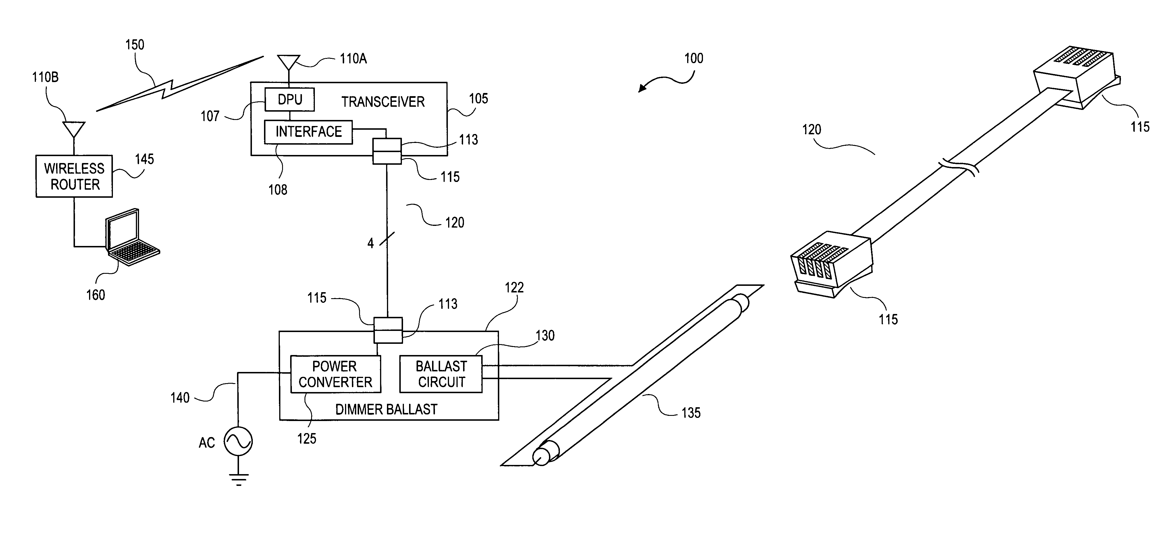
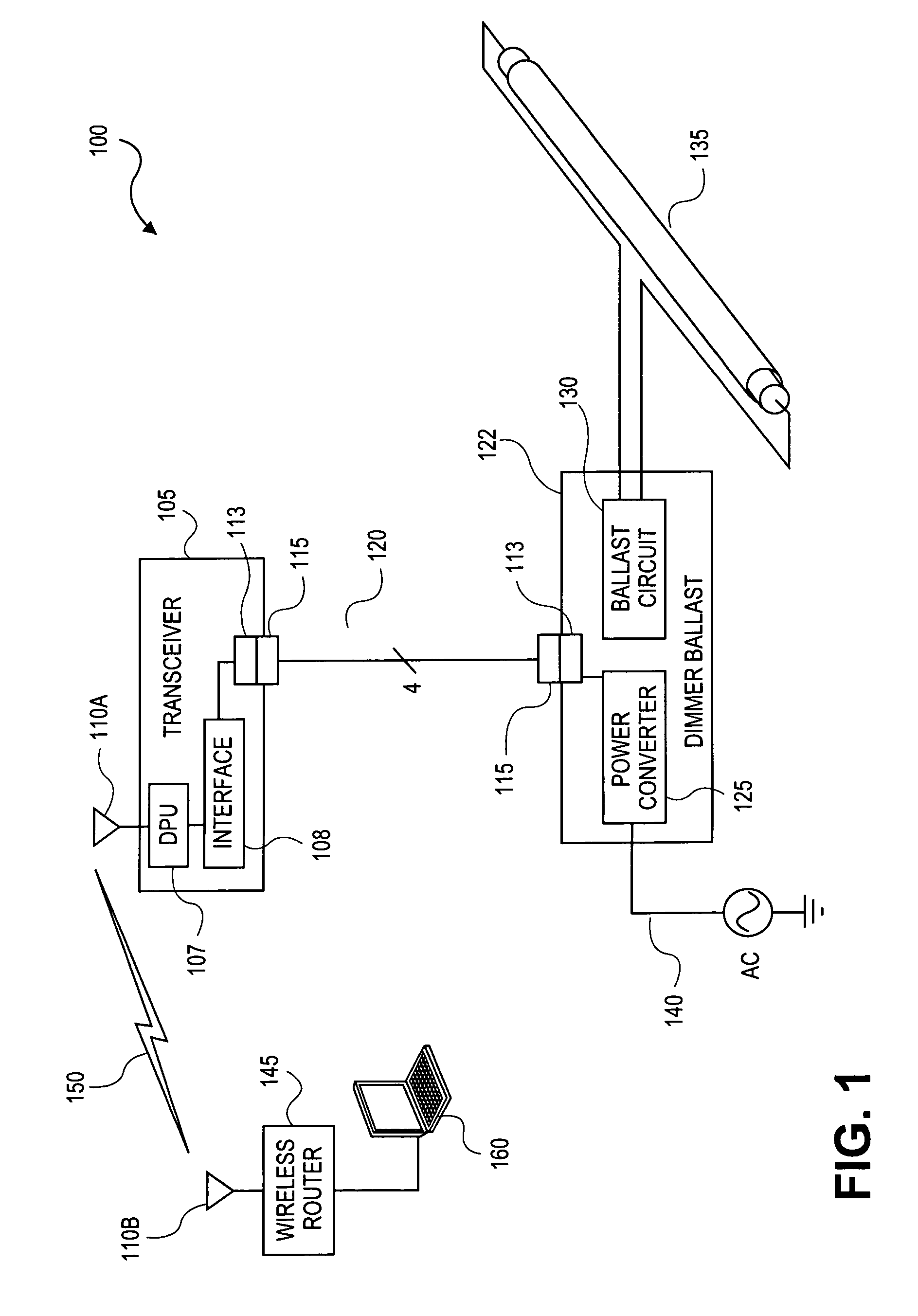
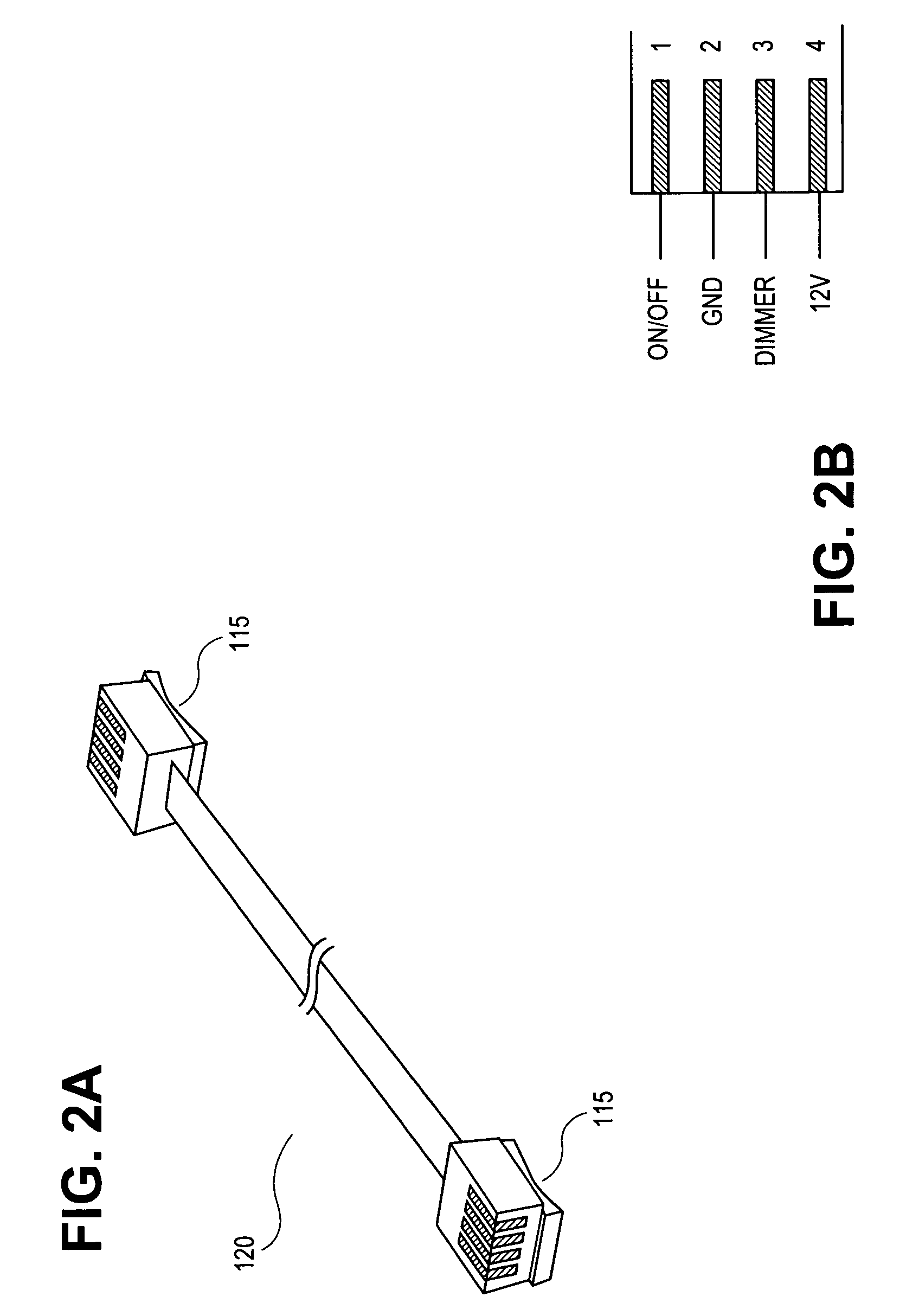
[0030]The present invention involves the use of a standard interface that provides wireless control of a ballast while minimizing the electromagnetic interference that a ballast transformer would impart on a wireless transceiver. The standard interface enables different lighting components, such as motion sensors, light harvesting sensors, relays, etc., to derive power, such as DC power, from the ballast and provide control signals, such as dimming control, to the ballast. The standard interface enables one to easily design and install one or more lighting systems for a room with minimal invasive wiring. Further, by using modular components that connect to the standard interface, and a standard interface cable, a building can have a variety of lighting configurations in different rooms while minimizing the number of different parts to maintain in inventory. Additionally, by using modular components with standard interfaces, and by incorporating wireless technology, existing building...


PUM


Abstract

Disclosed is a modular lighting system that incorporates wireless technology and a standard interface. The lighting system may be installed in new buildings or retrofitted into existing buildings in such a way that provides many lighting configurations and programmability options while minimizing the amount of new wiring. The system includes a transceiver that controls one or more lamps using a dimming ballast or a relay and a low cost ballast. The dimming ballast, and the relay (if used) provide low voltage power to the transceiver over a cable having a standard interface, such as an RJ11 telephone jack. The transceiver provides on / off switching control and dimmer control, through the same cable, to the relay or dimming ballast. The transceiver can be located in the same room as the lamps it controls, or remotely located. A central computer or controller can control multiple transceivers over a wireless link.

Description

BACKGROUND OF THE INVENTION[0001]1. Field of the Invention[0002]The present invention generally relates to lighting systems. More particularly, the present invention relates to lighting systems for residential or commercial structures in which energy conservation and ease of upgrading existing lighting systems are major concerns.[0003]2. Discussion of the Related Art[0004]Central lighting control systems, as used in commercial buildings, automatically turn lights on and off based on time of day. Many lighting control systems have included motion sensors and light harvesting sensors, which provide additional control in turning lights on and off. Motion sensors are typically used in areas, such as hallways or storage rooms, in which people are occasionally present. Light harvesting sensors, typically used in exterior offices with windows, turn lights on and off based on the presence of ambient sun light. The additional control provided by motion sensors and light harvesting sensors is...

Claims


Application Information

Patent Timeline
Patent Type & Authority Patents(United States)
IPC IPC(8): H05B37/02
CPCH05B37/0272H05B47/19H05B47/195
Inventor BUDIKE, JR., LOTHAR E. S.
Owner BUDIKE JR LOTHAR E S
Why Eureka
Try Eureka